
A Circularly Polarized Antenna Based on Ridge-Gap Waveguide

A circularly polarized antenna and gap waveguide technology, which is applied to slot antennas, antenna unit combinations with different polarization directions, antennas and other directions, can solve the problems of complex antenna structure, high processing difficulty and high production cost, and achieve high-efficiency radiation, Easy to process the antenna, satisfying the effect of the structure

Active Publication Date: 2020-05-22
XIDIAN UNIV
View PDF9 Cites 0 Cited by
  • Summary
  • Abstract
  • Description
  • Claims
  • Application Information

AI Technical Summary

Problems solved by technology

[0003] To sum up, the problems existing in the prior art are: the current antenna has a complex structure, a relatively large volume, it is difficult to miniaturize, it is difficult to process, and the production cost is high

Method used


Image

  • A Circularly Polarized Antenna Based on Ridge-Gap Waveguide
  • A Circularly Polarized Antenna Based on Ridge-Gap Waveguide
  • A Circularly Polarized Antenna Based on Ridge-Gap Waveguide

Examples


Embodiment Construction

[0019] In order to make the object, technical solution and advantages of the present invention clearer, the present invention will be further described in detail below in conjunction with the examples. It should be understood that the specific embodiments described here are only used to explain the present invention, not to limit the present invention.

[0020] The application principle of the present invention will be described in detail below in conjunction with the accompanying drawings.

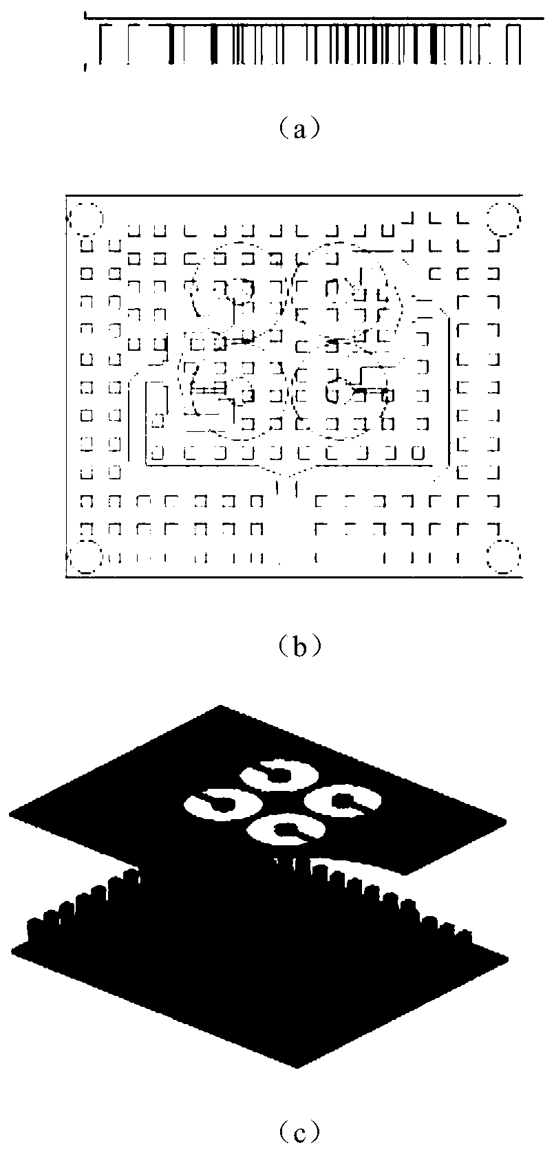
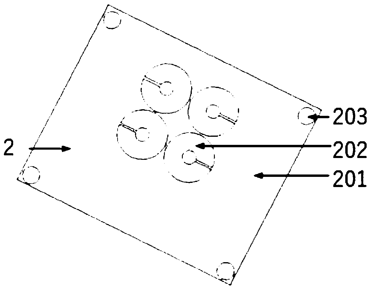
[0021] Such as figure 1 As shown, the circularly polarized antenna based on the ridge-gap waveguide provided by the embodiment of the present invention is composed of two layers from bottom to top, which are the feed network layer 1 and the slot radiation layer 2 in turn; the antenna is fed through the feed network through the main port 3 Layer 1 distributes and transmits energy to radiating layer 2.

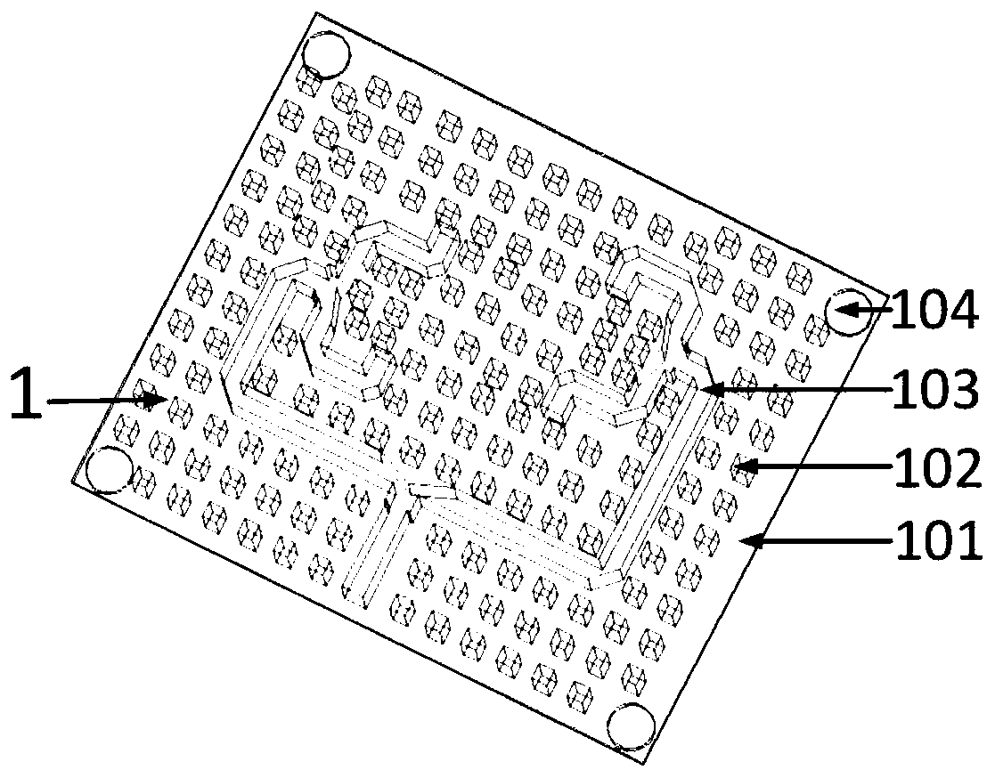
[0022] Such as figure 2 As shown, the power divider layer 1 of the antenna include...


PUM


Abstract

The invention belongs to the technical field of antennas, and discloses a ridge gap waveguide based circularly polarized antenna. The circularly polarized antenna is sequentially provided with a feed network layer and a radiation layer from bottom to top, and is characterized in that the feed network layer comprises a lower metal floor, periodically arranged metal pins, a power distribution metal ridge transmission structure and four through holes; the power distribution metal ridge transmission structure provides phase output with pairwise phase difference being 180 degrees according to the arrangement of four slot antennas; the slot radiation layer comprises an upper cover metal plate, four ring-shaped slots with braches and four through holes; and the four ring-shaped slotted slots with branches are distributed in a central symmetry manner, and the four slot antenna units radiate circularly polarized waves respectively and form a 2*2 circularly polarized antenna array. The impedance bandwidth of the antenna reaches up to 24.5%, the axis ratio bandwidth reaches up to 11.4%, and the gain in the frequency band can also meet requirements of practical applications. The ridge gap bandwidth based circularly polarized antenna stays at a high level in antennas of the same kind, and meets requirements of simple structure, small size and easy processing for antennas in practical applications.

Description

technical field [0001] The invention belongs to the technical field of antennas, in particular to a circularly polarized antenna based on a ridge-gap waveguide. Background technique [0002] With the development of microwave technology towards higher frequency bands, microwave devices tend to be miniaturized, integrated and mass-produced. Due to the problems of large volume, high cost and complicated debugging process, the application of metal waveguide components is severely restricted. Although the microstrip circuit has a compact structure, small size and low cost, its electromagnetic radiation is serious when it works in the high frequency band, and the transmission The loss is relatively large. As a new type of electromagnetic transmission structure, the ridge-gap waveguide structure is formed by arranging periodic electromagnetic band gaps around the metal ridges on a flat surface of the parallel plate waveguide. When the distance between the upper metal plate and the...

Claims


Application Information

Patent Timeline
Patent Type & Authority Patents(China)
IPC IPC(8): H01Q21/00H01Q21/24H01Q1/48H01Q1/50H01Q7/00H01Q13/10
CPCH01Q1/48H01Q1/50H01Q7/00H01Q13/10H01Q21/0006H01Q21/24
Inventor 李彤樊芳芳鄢泽洪雷娟高敬东
Owner XIDIAN UNIV
Learn More