Furnace chamber of a vertical tank type vacuum tempering furnace

A tempering furnace and hearth technology, applied in furnaces, furnace types, heat treatment furnaces, etc., can solve problems such as prone to failure, large energy reactive power loss, and long preheating time, so as to quickly enter the working state and reduce heat energy loss , Increase the effect of heat convection space

Active Publication Date: 2019-04-23
TIANJIN SEAGULL WATCH CO LTD
View PDF4 Cites 0 Cited by
  • Summary
  • Abstract
  • Description
  • Claims
  • Application Information

AI Technical Summary

Problems solved by technology

[0002] The vacuum tempering furnace used to produce watch hairsprings is an important heat treatment process in the production of watch hairsprings. It is not only a necessary means for the hairspring to be formed, but also determines the internal quality (physical properties) of the hairspring to a large extent. The furnace in its equipment Part is very important, which requires higher requirements for the constant uniformity and stability of the furnace working area, thermal energy effect, uniformity of heat radiation, and convenience of equipment maintenance. However, the traditional furnace currently used The structure can only meet the processing requirements of general products. For the processing of high-precision watch hairspring products, it is difficult for traditional equipment to meet product standards.
[0003] figure 1 It is a schematic diagram of the furnace wire distribution of the existing corundum tube furnace. The furnace wire elements shuttle in the annular hole groove on the inner wall of the corundum tube furnace, so that the furnace wire vortexed in the hole groove will affect the heat release effect due to the limitation of the circulation space. The thermal energy effect is low, which affects the thermal radiation of the furnace wire to the furnace, resulting in longer preheating time and greater energy reactive power loss. The furnace wire in the corundum tube is directly connected, and the furnace wire is a whole, so not only It is cumbersome, and every failure needs to be replaced as a whole, which makes the maintenance cost too high; in addition, this direct radiation situation is also an unfavorable factor that affects the constant and uniform furnace temperature
[0004] figure 2 It is a schematic diagram of the furnace wire distribution of the wall-mounted furnace with ceramic tile clamps. The furnace wire components are fixed on the outer wall of the furnace with ceramic tile clamps. The fastening screws and the furnace are sintered, resulting in difficulty in disassembly and deformation caused by the suspension of the furnace wire. , prone to failure, short service life, these bring many disadvantages to normal production

Method used


Image

  • Furnace chamber of a vertical tank type vacuum tempering furnace
  • Furnace chamber of a vertical tank type vacuum tempering furnace
  • Furnace chamber of a vertical tank type vacuum tempering furnace

Examples


Embodiment 1

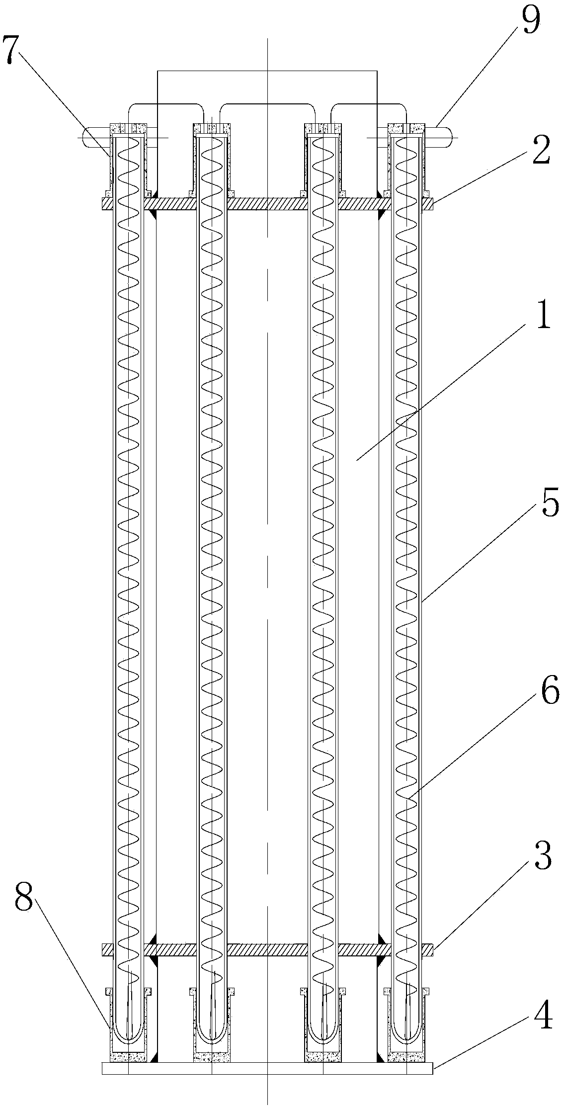
[0027] Embodiment 1: as image 3 As shown, the hearth of the vertical tank type vacuum tempering furnace of the present invention includes a furnace liner 1, a positioning plate, and a plurality of quartz glass tubes; the furnace liner 1 is processed with a positioning platform for installing a positioning plate, and the positioning plate includes an upper The positioning plate 2 and the lower positioning plate 3, the surface of the upper positioning plate 2 and the lower positioning plate 3 are respectively processed with uniform positioning holes for installing the quartz glass tube 5 (the number of holes depends on the power of the furnace), and the quartz glass tube 5 Fixed in the positioning holes in the upper positioning plate 2 and the lower positioning plate 3, the positioning method of the quartz glass tube 5 is the upper and lower positioning plate type; the upper positioning plate 2 and the lower positioning plate 3 are respectively welded on the positioning platform...

Embodiment 2

[0029] Embodiment 2: as Figure 4 As shown, the difference between this embodiment and Embodiment 1 is that the positioning plate can only be the upper positioning plate 2, and the quartz glass tube 5 can only be fixed on the upper positioning plate 2, and the positioning method of the quartz glass tube 5 is the chassis Table hole type. Other components and design ideas are the same as those in Embodiment 1, and will not be repeated here.

[0030] Figure 5 It is the overall schematic diagram of the vertical tank type vacuum tempering furnace of the present invention. One end of the pipeline in the chamber enters the furnace cavity, and the other end is connected with the vacuum unit.

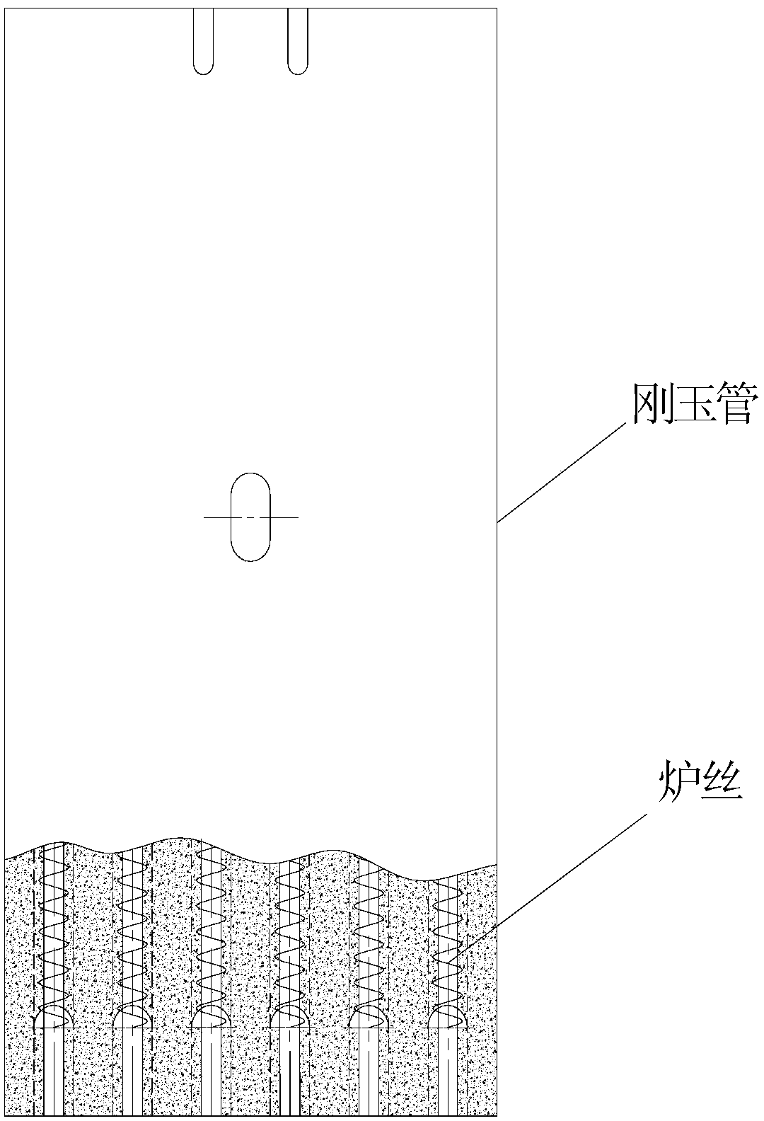
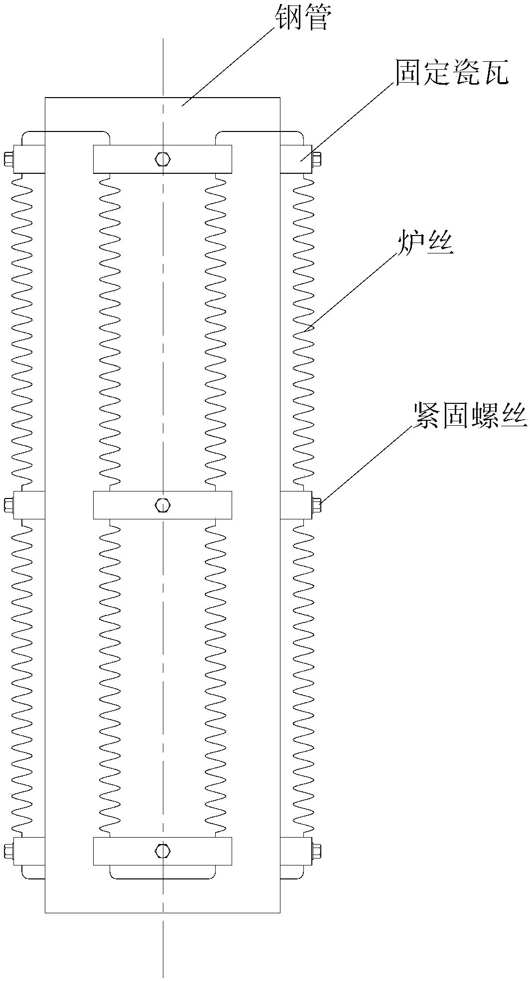
[0031] Because the present invention adopts stainless steel tube or ceramic material as the furnace liner, the furnace wire assembly with quartz tube protection is placed in the positioning plate at both ends of the steel tube furnace lining, and the furnace liner made of stainless steel or ...


PUM


Abstract

The invention discloses a hearth of a vertical tank type vacuum tempering furnace. The hearth comprises a hearth lining pipe, a positioning disc and multiple quartz glass tubes. The positioning disc is arranged on the hearth lining pipe, multiple furnace wire windings are placed in the multiple quartz glass tubes, furnace wires are in the suspension state, and each of the quartz glass tubes with the furnace wire windings is independently fixedly arranged in the positioning disc. The hearth has the beneficial effects that the hearth lining pipe made of stainless steel or ceramic materials can evenly achieve secondary heat radiation, the temperature of the work area of the hearth is more constant and even, watch hairsprings are subject to precise heat treatment, heat energy losses are reduced while the heat effect is improved, a steel structure is durable, safe and reliable, and the service life is prolonged. Due to single-winding loop winding of the furnace wire windings, heat source eddy is avoided, the heat convection space is increased, heat energy efficiency is high, temperature rise time is saved, and work state entrance is rapid. Due to single-winding loop winding of the furnace wire windings, when failures happen, independent replacement is convenient, the hearth is simple and convenient, and maintaining cost is reduced.

Description

technical field [0001] The invention relates to a vacuum heat treatment equipment; in particular, it relates to a furnace chamber structure in a vertical pot vacuum tempering furnace equipment for producing watch hairsprings. Background technique [0002] The vacuum tempering furnace used to produce watch hairsprings is an important heat treatment process in the production of watch hairsprings. It is not only a necessary means for the hairspring to be formed, but also determines the internal quality (physical properties) of the hairspring to a large extent. The furnace in its equipment Part is very important, which requires higher requirements for the constant uniformity and stability of the furnace working area, thermal energy effect, uniformity of heat radiation, and convenience of equipment maintenance. However, the traditional furnace currently used The structure can only meet the processing requirements of general products. For the processing of high-precision watch hai...

Claims


Application Information

Patent Timeline
Patent Type & Authority Patents(China)
IPC IPC(8): C21D1/773C21D9/00
CPCC21D1/773C21D9/0068
Inventor 杜庆鸣
Owner TIANJIN SEAGULL WATCH CO LTD
Why Eureka
Try Eureka