Selective laser sintering method and device based on surface light source
A technology of selective laser sintering and surface light source, applied in the field of additive manufacturing, can solve the problems of different powder sintering times, uneven sintering quality, limited processing range, etc., to achieve uniform molding quality, convenient operation, and improve efficiency.
- Summary
- Abstract
- Description
- Claims
- Application Information
AI Technical Summary
Problems solved by technology
Method used
Image
Examples
Embodiment 1
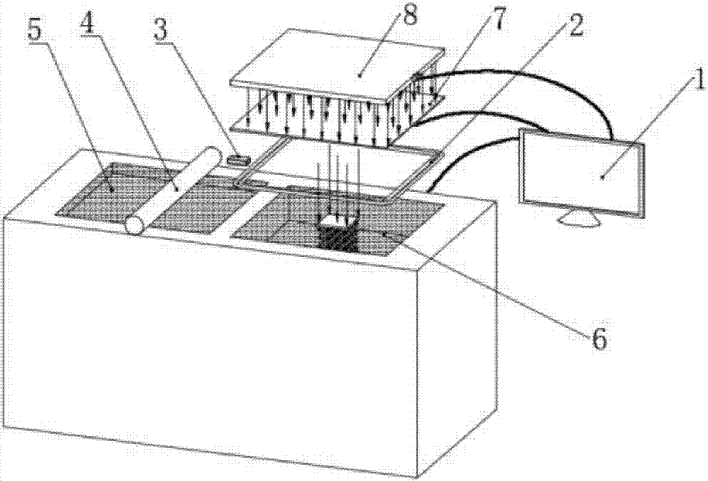
[0031] see figure 1 , Figure 4 , Figure 9 and Figure 10 , a selective area laser sintering device based on a surface light source, including a powder spreading system connected to a computer 1, a temperature control system, a light source and an optical path system, wherein the light source is an LED light source group 8, and the optical path system is composed of a TFT liquid crystal display 7. The powder system includes a drum 4, a powder supply cylinder 5, a molding cylinder 6, and a lifting table 11. The temperature control system includes a heater 2 and a temperature sensor 3. The LED light source group 8 includes a plurality of light emitting units 81, and the array of multiple light emitting units 81 Arrangement, a plurality of light emitting units 81 are electrically connected with a light source control unit 82 to control the lighting and extinguishing of the plurality of light emitting units 81, and each light emitting unit of the plurality of light emitting uni...
Embodiment 2
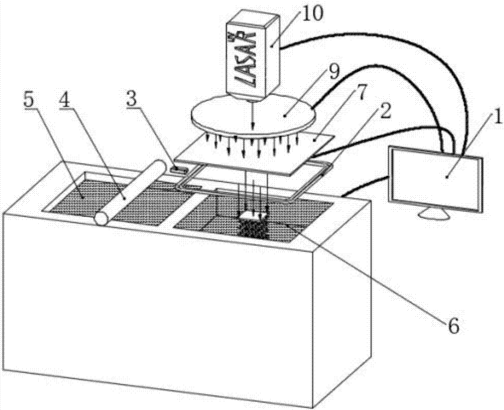
[0034] see figure 2 , Figure 5 , Figure 9 and Figure 10 , a selective laser sintering device based on a surface light source, including a powder spreading system connected to a computer 1, a temperature control system, a light source and an optical path system, wherein the light source is composed of a beam expander 9 and a laser 10. The optical path system consists of a TFT liquid crystal display 7, the powder spreading system includes a drum 4, a powder supply cylinder 5, a forming cylinder 6 and a lifting platform 11, and the temperature control system includes a heater 2 and a temperature sensor 3.
[0035] The work process of the present embodiment is: draw three-dimensional solid model in computer 1, carry out slice processing to three-dimensional solid by software, obtain the information of each section layer and show corresponding two-dimensional image on TFT liquid crystal screen 7; Two-dimensional image The corresponding solid cross-sectional area is a light-t...
Embodiment 3
[0037] see image 3 , Figure 6 , Figure 7 , Figure 8 , Figure 9 and Figure 10 , a selective area laser sintering device based on a surface light source, including a powder spreading system connected to a computer 1, a temperature control system, a light source and an optical path system, wherein the light source is composed of an ultraviolet LED light source group 8 and a light source control system 15, and the optical path system is composed of an optical fiber bundle 12, focusing fiber lens group 13 and imaging lens 14, powder spreading system includes drum 4, powder supply cylinder 5, molding cylinder 6 and lifting platform 11, temperature control system includes heater 2 and temperature sensor 3, the LED light source The group 8 includes a plurality of light emitting units 81 arranged in an array, and the light emitting units 81 are installed on the substrate 86 of the ultraviolet light source group.
[0038] The working process of the present embodiment is: draw a...
PUM
 Abstract
Description
Claims
Application Information
 - R&D
- Intellectual Property
- Life Sciences
- Materials
- Tech Scout
- Unparalleled Data Quality
- Higher Quality Content
- 60% Fewer Hallucinations
Browse by: Latest US Patents, China's latest patents, Technical Efficacy Thesaurus, Application Domain, Technology Topic, Popular Technical Reports.
© 2025 PatSnap. All rights reserved.Legal|Privacy policy|Modern Slavery Act Transparency Statement|Sitemap|About US| Contact US: help@patsnap.com


