Efficient air-dissolving air floating machine

A dissolved air flotation machine and high-efficiency technology, which is used in dissolution, mixer, flotation water/sewage treatment, etc. The problems such as the completion of the floating separation, the short contact time between the bubbles and the suspended matter, etc., achieve the effect of enhancing the adaptability, reducing the floor space and enhancing the stability.

Inactive Publication Date: 2017-11-24
湖南美奕机电科技有限公司
View PDF7 Cites 2 Cited by
  • Summary
  • Abstract
  • Description
  • Claims
  • Application Information

AI Technical Summary

Problems solved by technology

Bubbles and particles complete the collision and adhesion process in the contact chamber, the micro-bubbles flow in the same direction as the upwardly flowing sewage, the contact time between the bubbles and the suspended matter is short, and the adhesion effect of the bubbles is poor, especially when oil or suspended particles in the sewage More and loose flocs
[0004] The counter-current air flotation device generally has a single contact chamber, in which the upward micro-bubbles and the downward-flowing raw water flow in the opposite direction, and the descending suspended matter and the rising air bubbles are in reverse contact, so that the air bubbles and the suspended matter adhere to each other. The micro-bubbles and particles can complete the collision process very well, but due to the downward flow force of the raw water, the micro-bubbles and particles cannot adhere well to form a stable foam floc, or after the adhesion, the heterogeneous flow force of the raw water Under the action of desorption, the formed bubbles and flocs cannot complete the floating separation process well.

Method used


Image

  • Efficient air-dissolving air floating machine

Examples


Embodiment 1

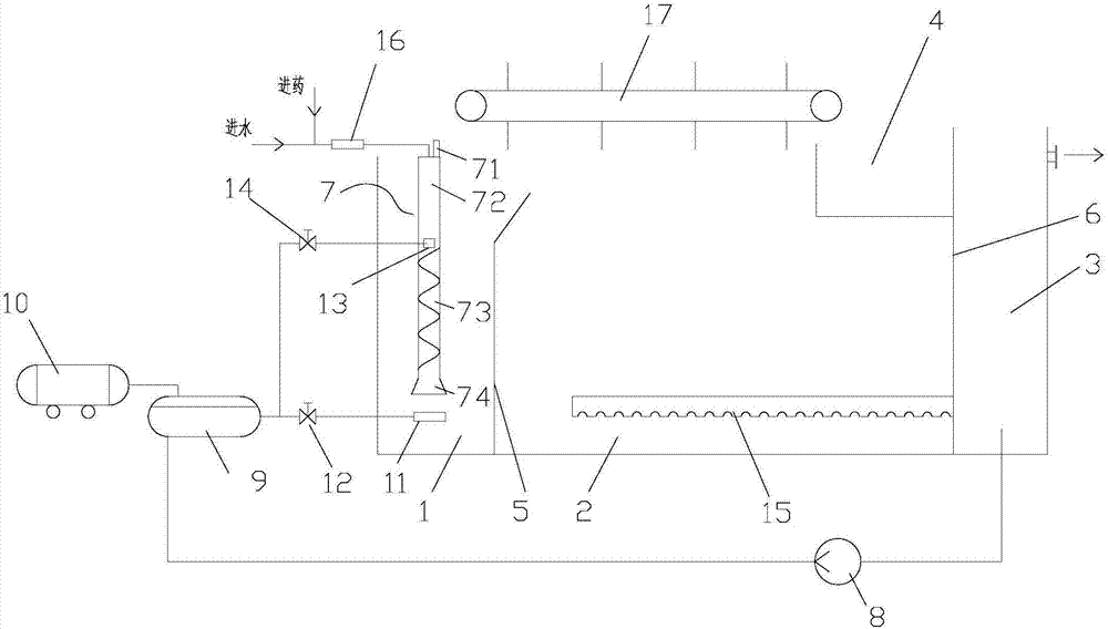
[0025] like figure 1 As shown, a kind of high-efficiency dissolved air flotation machine of the present invention comprises air flotation tank, bubble release pipe 7, slag scraping device 17, dissolved air system, clear water pipe 15, first bubble releaser 11, second bubble releaser 13, Water inlet and dosing port; the air flotation tank is provided with a first partition 5 and a second partition 6, and the first partition 5 and the second partition 6 divide the air flotation tank into a contact pool 1 and a separation pool 2 in sequence and clear water pool 3; the clear water pool 3 is provided with a water outlet; the scum pool 4 is arranged above the separation pool 2; the slag scraping device 17 is located above the separation pool 2, and the slag scraping device 17 includes a chain, two Two sprockets and multiple scum scrapers are connected by a chain, and multiple scum scrapers are fixed on the chain, and the sprocket drives the scum scrapers on the chain to scrape the s...


PUM


Abstract

The invention discloses an efficient air-dissolving air floating machine which comprises an air floating tank, a bubble release tube, a slag scraping device, an air dissolving system, a clear water tube, a first bubble release device, a second bubble release device, a water inlet and a dosing port. A first partition plate and a second partition plate in the air floating tank divide the air floating tank into a contact tank body, a separating tank body and a clear water tank body in sequence, the bubble release tube is vertically mounted in the contact tank body, the bubble release tube comprises an exhaust tube section, a vertical tube section, a rotational flow tube section and a trumpet-shaped tube section which communicate with one another in sequence, wastewater in the bubble release tube collides with microbubbles in reverse directions, are rotationally blended with the microbubbles, and adhere to the microbubbles in the same direction in the contact tank body, microbubble-particle interaction is improved, the adhesion ability of the microbubbles is enhanced, the stability of bubble flocs is improved, the efficiency of colliding among the microbubble-particles is remarkably improved, and the adaptability to changes of the quality of the wastewater is remarkably improved. In addition, the air floating machine has the advantages of being small in occupied area and compact in structure.

Description

technical field [0001] The invention relates to the field of sewage treatment equipment, in particular to a high-efficiency dissolved air flotation machine. Background technique [0002] Dissolved air flotation technology is a solid-liquid separation technology, which has the characteristics of high processing efficiency, short start-up time and small footprint, and is widely used in the field of water treatment. The complete dissolved air flotation technology includes three basic processes: flocculation process, dissolved air degassing process and bubble-floc aggregate formation and separation process. [0003] According to the flow direction and contact mode of dissolved air water and sewage, the dissolved air flotation process is divided into cocurrent flow process and reverse flow process. The co-flow air flotation machine generally includes a flocculation reaction tank, a contact tank and a separation tank. The sewage first enters the flocculation reaction tank and fu...

Claims


Application Information

Patent Timeline
Patent Type & Authority Applications(China)
IPC IPC(8): C02F1/24B01F5/06
CPCC02F1/24B01F25/40B01F2101/305
Inventor 不公告发明人
Owner 湖南美奕机电科技有限公司
Why Eureka
Try Eureka