Glow-ion-nitriding inner-hot-wall type vacuum ion nitriding furnace and utilization method thereof

A technology of glow ion infiltration and ion nitriding, which is applied in the direction of metal material coating process, coating, solid diffusion coating, etc. Uniformity and other issues to achieve the effect of uniform temperature

Inactive Publication Date: 2017-11-24
武汉武热研热处理科技有限公司
View PDF6 Cites 5 Cited by
  • Summary
  • Abstract
  • Description
  • Claims
  • Application Information

AI Technical Summary

Problems solved by technology

[0003] The traditional vacuum furnace body is a cold fireplace structure, and there are many defects in the use process. The main performance is that the temperature field in the furnace is seriously uneven, and the metal parts placed in the effective working area of ​​the vacuum furnace body during the production process, especially the upper and lower parts and the cathode The temperature of the inner and outer rings of the disk will be uneven. When the parts are installed in the furnace for nitriding processing, the temperature is generally about 520°C. However, the parts in the upper and lower areas of the furnace and the inner and outer rings of the parts have a large temperature difference. The temperature deviation causes the surface hardness and the depth of the nitride layer to be uneven; the current improvement methods mainly include: (1) by adjusting the placement of the parts, adding auxiliary cathodes, and adjusting the spacing of the parts according to the temperature of the parts to improve The temperature uniformity of the processed parts in the furnace; (2) The temperature uniformity in the furnace is improved by adding resistance auxiliary heating in the nitriding furnace, but the auxiliary heating is a one-way control mode (one-way heating without cooling), when the furnace Internally, due to the structure, placement of parts, and the partial injection of the output power of the ion heating power supply due to the different surface areas of the parts, the measured temperature of a certain section of the temperature will still be higher than The set temperature of the control has a dead zone and the temperature cannot be adjusted

Method used


Image

  • Glow-ion-nitriding inner-hot-wall type vacuum ion nitriding furnace and utilization method thereof
  • Glow-ion-nitriding inner-hot-wall type vacuum ion nitriding furnace and utilization method thereof
  • Glow-ion-nitriding inner-hot-wall type vacuum ion nitriding furnace and utilization method thereof

Examples


Embodiment Construction

[0029] The implementation of the present invention will be described in detail below in conjunction with the accompanying drawings, but they do not constitute a limitation to the present invention, and are only examples. At the same time, the advantages of the present invention are clearer and easier to understand through the description.

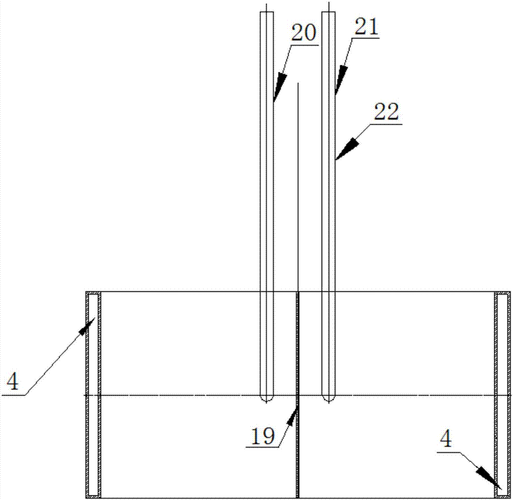
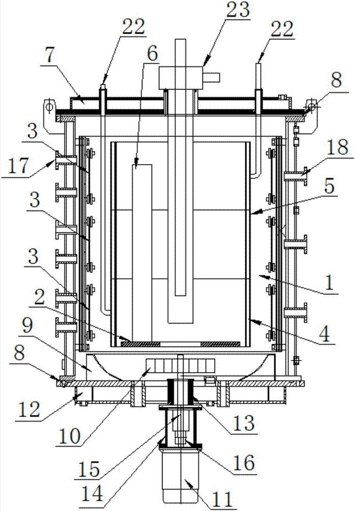
[0030]Referring to the accompanying drawings, it can be seen that the glow ion nitriding internal heating wall vacuum ion nitriding furnace includes a furnace cylinder body 1, a cathode plate 2, and a resistance heating element 3. It is characterized in that it also includes an inner heating wall 4; the inner heating wall 4 is ring-shaped, The inner heating wall 4 is located in the furnace body 1, and its lower end is flush with the lower end of the cathode disk 2. The inner diameter of the inner heating wall 4 is larger than the outer diameter of the cathode disk 2. Three or more inner heating walls 4 stacked along the axial direction form ...


PUM


Abstract

The invention discloses a glow-ion-nitriding inner-hot-wall type vacuum ion nitriding furnace and a utilization method thereof. The vacuum ion nitriding furnace comprises a furnace cylinder, a resistance heating elements and inner hot walls. The inner hot walls which are annular are positioned in the furnace cylinder, inner diameters of the inner hot walls are larger than outer diameters of cathode discs, three or more of the inner hot walls overlapped axially form an inner hot wall assembly in the furnace cylinder, the upper end of each inner hot wall assembly is positioned above the lateral upper end of the resistance heating elements while the lower end of each inner hot wall assembly is positioned below the lateral upper end of the resistance heating elements, the cathode discs are positioned in an annular area formed by the inner hot wall assemblies, and to-be-machined parts are positioned on the cathode discs and in the annular area formed by the inner hot wall assemblies. The resistance heating elements are positioned outside the inner hot wall assemblies. The glow-ion-nitriding inner-hot-wall type vacuum ion nitriding furnace has the advantage of reduction of temperature difference between inside and outside as well as between the upper portion and the lower portion.

Description

technical field [0001] The invention relates to the field of chemical heat treatment of metal materials, more specifically it is a glow ion nitriding inner hot wall vacuum ion nitriding furnace. The invention also relates to the use method of the glow ion nitriding inner hot wall vacuum ion nitriding furnace. Background technique [0002] Most of the traditional glow ion nitriding furnaces use cold wall vacuum furnaces, usually with double-layer structure, welded with Q235 steel plates, and a 30-50 mm wide interlayer between the two layers of steel plates is left as a water-through layer. Continuous feeding of cooling water (the cooling water can be recycled after passing through the heat exchanger) is used to cool the vacuum nitriding furnace body to ensure the long-term use of the seals at low temperature. The furnace body has a simple structure and is made of low-carbon steel plate with low cost and maintenance Simple maintenance and other advantages have been widely use...

Claims


Application Information

Patent Timeline
Patent Type & Authority Applications(China)
IPC IPC(8): C23C8/36
CPCC23C8/36
Inventor 黄健
Owner 武汉武热研热处理科技有限公司
Why Eureka
Try Eureka