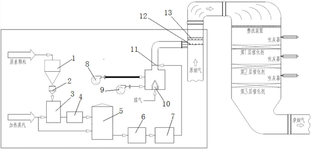
Urea pyrolysis and ejection system used for low-temperature flue gas SCR denitration
A low-temperature flue gas, injection system technology, applied in the preparation/separation of ammonia, inorganic chemistry, ammonia compounds, etc., can solve the problems of heat consumption, high use cost, high operating cost, and achieve convenient implementation, reliable system and simple process. Effect
- Summary
- Abstract
- Description
- Claims
- Application Information
AI Technical Summary
Problems solved by technology
Method used
Image

Examples
Embodiment Construction
[0022] Below in conjunction with specific embodiment, further illustrate the present invention. It should be understood that these examples are only used to illustrate the present invention, not to limit the protection scope of the present invention. Improvements and adjustments made by those skilled in the art according to the present invention in practical applications still belong to the protection scope of the present invention.
[0023] The SCR denitrification catalyst has high denitrification performance, but correspondingly requires a relatively high reaction temperature. In the low-temperature flue gas SCR denitrification system, in order to ensure the denitrification efficiency of the SCR denitrification system, it is usually necessary to set up a heating furnace for the denitrification of the original flue gas. For reheating, the heating furnace generally uses blast furnace gas / coke oven gas / natural gas and other combustion media. The high-temperature flue gas produ...
PUM
 Abstract
Description
Claims
Application Information
 - R&D
- Intellectual Property
- Life Sciences
- Materials
- Tech Scout
- Unparalleled Data Quality
- Higher Quality Content
- 60% Fewer Hallucinations
Browse by: Latest US Patents, China's latest patents, Technical Efficacy Thesaurus, Application Domain, Technology Topic, Popular Technical Reports.
© 2025 PatSnap. All rights reserved.Legal|Privacy policy|Modern Slavery Act Transparency Statement|Sitemap|About US| Contact US: help@patsnap.com