
Manufacturing method of mems chip packaging structure capable of stress release by inversion assembly

A chip packaging structure and manufacturing method technology, applied in the direction of assembling microstructure devices, microstructure technology, microstructure devices, etc., can solve the problems of increasing the complexity and cost of processing, chip deformation, increasing the total thickness of the device, etc., to increase processing. Number and complexity of steps, effect of increasing packaging cost, reducing impact

Active Publication Date: 2019-06-04
NORTH ELECTRON RES INST ANHUI CO LTD
View PDF24 Cites 0 Cited by
  • Summary
  • Abstract
  • Description
  • Claims
  • Application Information

AI Technical Summary

Problems solved by technology

[0019] Invention patents "MEMS Inertial Sensor Package Structure with Stress Isolation", "Package Structure That Can Reduce Package Stress", "Chip Attach Stress Isolation", "A Pressure Sensor Based on Silicon-Silicon Bonding Isolated Package Stress", " A Thermal Stress Isolation Structure for MEMS Devices" and "A MEMS Device and Its Manufacturing Method" all add a special isolation structure under the existing MEMS bare chip to reduce the impact of packaging stress on chip deformation. The disadvantage of the method is that an additional structural layer is required, thus increasing the overall thickness of the device
Invention patent "Method for Reducing MEMS Chip Packaging Stress Through Back Patterning" Although the etching process is used to process a special graphic structure on the back of the chip, which reduces the contact area between the chip and the package, there are still many parts on the bottom of the chip The problem of fixed connection with the shell, multi-position fixed connection will still generate thermal stress, resulting in deformation of the chip
Its disadvantage is that the packaging cavity and blocking filler need to be specially customized, which increases the processing complexity and cost

Method used


Image

  • Manufacturing method of mems chip packaging structure capable of stress release by inversion assembly
  • Manufacturing method of mems chip packaging structure capable of stress release by inversion assembly
  • Manufacturing method of mems chip packaging structure capable of stress release by inversion assembly

Examples


Embodiment Construction

[0045] The present invention will be further described below in conjunction with the accompanying drawings. The following examples are only used to illustrate the technical solution of the present invention more clearly, but not to limit the protection scope of the present invention.

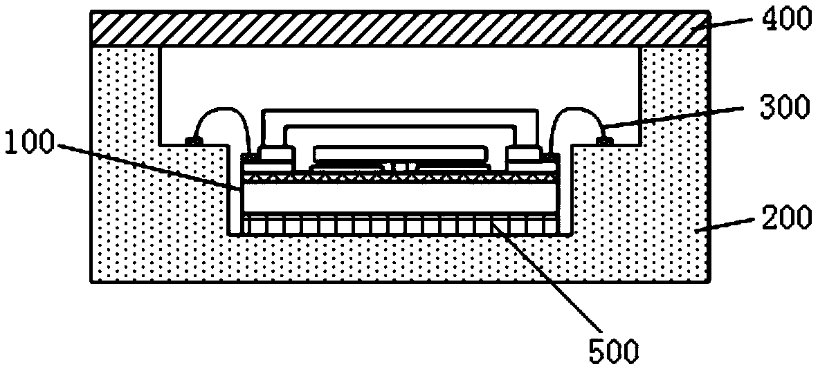
[0046] Traditional variable-pitch MEMS capacitive sensors such as figure 1 shown. The lower electrode of the MEMS capacitive sensor is directly fixed on the silicon dioxide isolation layer, and the silicon dioxide isolation layer is fixed on the silicon substrate. The upper electrode of the MEMS capacitive sensor (that is, the MEMS sensitive structural mass) is suspended on the lower electrode through the support of the central anchor point structure. The upper electrode and the lower electrode form a capacitance relative to each other. When there is an external sensitive quantity input, the capacitance value formed by the upper electrode and the lower electrode changes, and the detection of t...


PUM


Abstract

The invention discloses a manufacturing method of an inversely assembled and stress-releasing MEMS chip packaging structure. The manufacturing method comprises the steps of processing conductive through holes in a silicon substrate of a wafer A and then oxidizing the wafer A to form a silicon dioxide protective layer; removing the silicon dioxide protective layer on the surface of a silicon electrode layer and processing an anchor point structure and a sensitive structure cavity on the silicon electrode layer; processing an electrode structure inside the sensitive structure cavity; bonding the silicon electrode layer of another wafer B to the silicon electrode layer of the wafer A by adopting a bonding technology; removing the silicon substrate and the silicon dioxide isolation layer of the wafer B; processing a sensitive structure on the silicon electrode layer of the wafer B; bonding a silicon cap to the silicon electrode layer of the wafer B; processing a stress release groove in the silicon substrate of the wafer A by adopting a deep groove etching technology; placing a chip inversely, fixing the surface of the silicon cap to the bottom surface of a ceramic tube shell cavity in an gluing or bonding manner so as to enable the conductive through holes and ceramic tube shell pins to be electrically connected with each other by bonding metal wires, and finally sealing the ceramic tube shell by adopting a kovar alloy cover plate. The manufacturing method of the inversely assembled and stress-releasing MEMS chip packaging structure has the advantages that the packaging technology is simple and the packaging cost is not increased remarkably; and the manufacturing method is easy to realize.

Description

technical field [0001] The invention relates to a MEMS chip packaging structure, which belongs to the technical field of MEMS. Background technique [0002] MEMS (Micro Electro Mechanical System) capacitive sensors have the advantages of small size, light weight, low power consumption, and low cost, and are widely used. The MEMS capacitive sensor realizes the measurement of the corresponding physical quantity to be measured by measuring the capacitance change formed by the tiny sensitive structure. Usually, MEMS sensors need to be packaged in a certain structure to provide the electrical connection, mechanical connection and corresponding chemical environmental protection required by the sensor. [0003] Metal package, plastic package and ceramic package are the three most common packaging forms of MEMS chips. Because ceramic packages have the advantages of good thermal conductivity and air tightness, ceramic packages are most widely used. [0004] The packaging structure...

Claims


Application Information

Patent Timeline
Patent Type & Authority Patents(China)
IPC IPC(8): B81B7/02B81C3/00G01D5/24
CPCB81B7/02B81B2201/0221B81C3/001B81C2203/01B81C2203/03G01D5/24
Inventor 凤瑞
Owner NORTH ELECTRON RES INST ANHUI CO LTD
Learn More