Production structure of float glass

A technology for producing structure and float glass, applied in glass production, glass manufacturing equipment, chemical instruments and methods, etc., can solve the problems of glass liquid temperature difference, single production line product, inability to effectively control glass liquid temperature, etc., to meet the energy saving requirements The effect of reducing consumption, reducing floor space, and meeting the diverse needs of the market

Pending Publication Date: 2017-12-08
长利玻璃洪湖有限公司
View PDF9 Cites 5 Cited by
  • Summary
  • Abstract
  • Description
  • Claims
  • Application Information

AI Technical Summary

Problems solved by technology

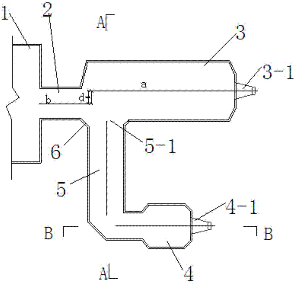
[0006] In the present invention, one or more branch channels and cooling parts are connected to one side of the front end of the cooling part of the main line (the rear end of the neck), so that a glass melting furnace is equipped with multiple production lines, that is, one main line plus one or more branch lines. At the same time, according to The various outputs of the main line and the branch line need to properly shift the central axis of the cooling part of the main line to the opposite side of the cooling part of the branch line, so that more hot glass from the neck can directly enter the channel of the branch line, thereby increasing the outlet temperature of the branch line and meeting the requirements of the branch line float process. The molding temperature needs to break through the difficult problem of not being able to effectively control the temperature of the glass melt, and solve the difference in the temperature of the glass melt caused by the difference in the flow distance of the main line and the branch line glass and the difference in the pulling amount of the main line and the branch line, and realize the large-tonnage float glass melting. The multi-line production of one kiln solves the problem of single product in the existing production line while saving energy and reducing consumption. A glass melting kiln can be used to produce different types of glass at the same time, meeting the diverse needs of the market

Method used


Image

  • Production structure of float glass
  • Production structure of float glass
  • Production structure of float glass

Examples


Embodiment Construction

[0017] The present invention will be further described in detail below in conjunction with the accompanying drawings to facilitate a clearer understanding of the present invention, but they do not limit the present invention.

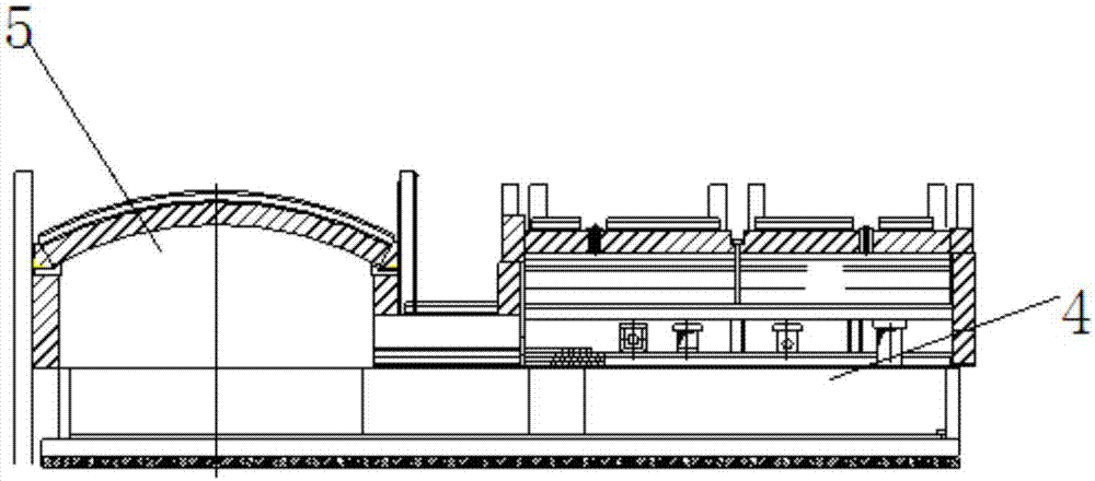
[0018] Such as figure 1 As shown, a float glass production structure includes a glass melting furnace 1, the glass melting furnace 1 is connected to a neck 2, and the neck is provided with a neck water bag and an agitator, and the neck 2 is connected to the cooling part of the main line 3. One side of the main line cooling part 3 is connected with a branch line channel 5, one end of the branch line channel 5 is connected with the main line cooling part 3, and the other end is connected with the branch line cooling part 4, and the branch line channel 5 is connected with the main line cooling part 3 The connection port 5-1 is located in the first half of the main line cooling part 3. In order to reduce the retention of glass liquid, a diversion angle 6 is...


PUM


Abstract

The invention discloses a production structure of float glass. The production structure of the float glass comprises a glass melting furnace, wherein the glass melting furnace is connected with a neck, the neck is connected with a main line cooling part, one or more branch line cooling part is connected onto one side of the main line cooling part, the central axis of the main line cooling part is offset from the central axis of the glass melting furnace, and the central axis of the main line cooling part is offset to the side opposite to the branch line cooling part. In the invention, the central axis of the main line cooling part is properly offset to the opposite side of the branch line cooling part, so that more hot glass from the neck directly enters into a branch line channel to solve the temperature difference of glass liquid caused by different drawing quantities of a main line and a branch line so as to achieve one-kiln multi-line production of a large-tonnage float glass melting furnace, and meet market diversified demands while saving energy and reducing consumption.

Description

technical field [0001] The invention relates to a float glass production line, in particular to a float glass production structure. Background technique [0002] At present, the layout of float glass production lines at home and abroad is one kiln and one line. From the front to the back, there are float glass melting furnaces, necks, cooling parts, runners, tin baths, annealing kilns and cold ends. Two production lines are arranged in one factory building, and two glass furnaces must be installed respectively, and one furnace matches one tin bath. Corresponding combustion equipment, thermal instrumentation, automatic control system, feeding machine, fan and sluice plate and other process equipment need to use two sets, which has a large investment cost and does not meet the national energy saving and emission reduction requirements. At the same time, large glass melting furnaces, such as those above 900T / D, produce a single product, especially for the production of special...

Claims


Application Information

Patent Timeline
Patent Type & Authority Applications(China)
IPC IPC(8): C03B7/01
CPCC03B7/01Y02P40/57
Inventor 易乔木刘怀艺王桂荣陈德成朴血柳仕旭谭利宫俊峰关岭
Owner 长利玻璃洪湖有限公司
Why Eureka
Try Eureka