

Photocatalytic aerated disinfecting and fertilizer supplementing device and method
A technology of disinfection device and photocatalysis, applied in fertilization device, botanical equipment and method, nitrogen fertilizer and other directions, to achieve the effect of improving transformation efficiency, avoiding root rot phenomenon and promoting growth
- Summary
- Abstract
- Description
- Claims
- Application Information
AI Technical Summary
Problems solved by technology
Method used
Image

Examples
Embodiment 1
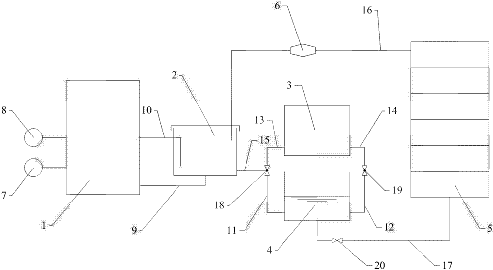
[0038] Such as figure 1 The device shown includes: a micro-nano bubble generating device 1, a photocatalytic disinfection device 2, a nitrification reaction device 3, a regulating tank 4, a soilless cultivation bed 5, an ultraviolet lamp 21, an aeration head 23, and the like.
[0039] The air source 7 and the water source 8 respectively enter the micro-nano-bubble generating device 1 through the air source interface and the liquid interface of the micro-nano-bubble generating device 1, and are fully mixed inside the device to form a gas-liquid mixed fluid, and one end of the gas-liquid mixed fluid pipeline 9 is connected to One end of the gas-liquid mixed fluid outlet of the micro-nano bubble generating device is connected to the aeration head 23 at the bottom of the photocatalytic disinfection device 2 . The gas-liquid mixed fluid formed in the micro-nano-bubble generating device 1 passes through the gas-liquid mixed fluid pipeline 9 and the aeration head 23 to form micro-nan...
Embodiment 2
[0041] Such as Figure 6 The device shown includes: a micro-nano bubble generating device 1, a photocatalytic disinfection device 2, a regulating tank 4, an ultraviolet lamp 21, an aeration head 23, an irrigation device 51, and the like.
[0042] The air source 7 and the water source 8 respectively enter the micro-nano-bubble generating device 1 through the air source interface and the liquid interface of the micro-nano-bubble generating device 1, and are fully mixed inside the device to form a gas-liquid mixed fluid, and one end of the gas-liquid mixed fluid pipeline 9 is connected to One end of the gas-liquid mixed fluid outlet of the micro-nano bubble generating device is connected to the aeration head 23 at the bottom of the photocatalytic disinfection device 2 . The gas-liquid mixed fluid formed in the micro-nano-bubble generating device 1 passes through the gas-liquid mixed fluid pipeline 9 and the aeration head 23 to form micro-nano-bubble water and enters the photocata...
Embodiment 3
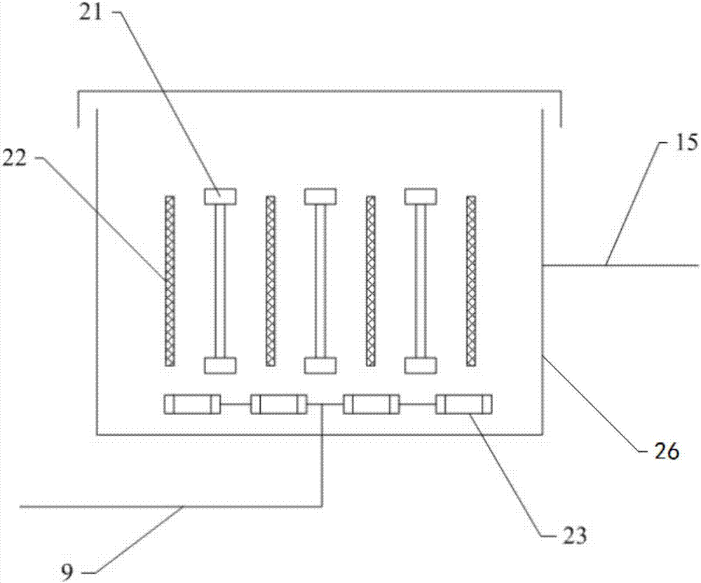
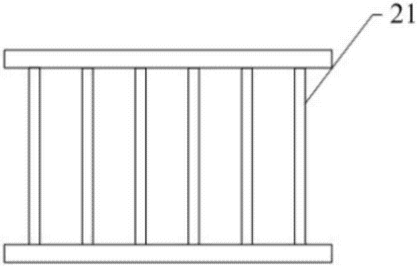
[0044] On the basis of Example 1 or Example 2, the photocatalytic disinfection device 2 includes: a photocatalytic pool 26, an ultraviolet lamp 21 positioned in the photocatalytic pool 26, a catalyst carrier grid 22 and a catalyst carrier grid 22 attached to The photocatalyst on the catalyst carrier grid 22 and the ultraviolet lamp 21 are alternately arranged, and the aeration head 23 is located in the photocatalytic pool 26 and below the catalyst carrier grid 22 and the ultraviolet lamp 21 .
[0045] The catalyst carrier grid 22 is made of at least one of porous glass, glass fiber, glass plate and metal.
PUM
 Abstract
Description
Claims
Application Information