
A broadband dispersion control fiber and its dispersion control method

A dispersion-flattened fiber and broadband technology, applied in cladding fibers, optics, light guides, etc., can solve the problems of complex two-layer structure and dispersion-flattening control, and achieve rich nonlinear effects, few control parameters, and high chemical stability. Effect

Inactive Publication Date: 2020-10-09
TIANJIN UNIV
View PDF14 Cites 0 Cited by
  • Summary
  • Abstract
  • Description
  • Claims
  • Application Information

AI Technical Summary

Problems solved by technology

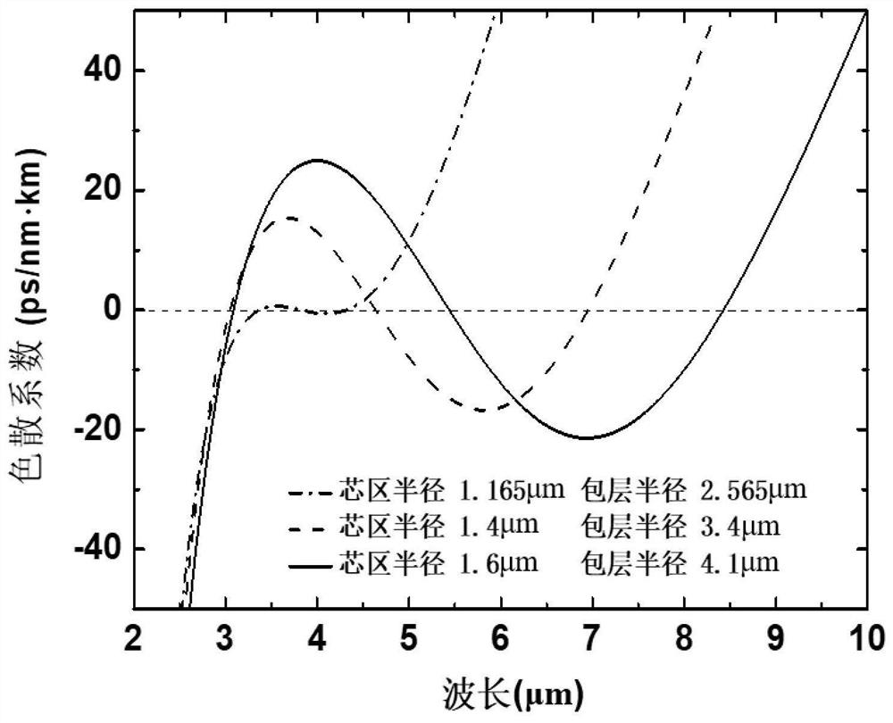
Although the optical fibers with the above two multilayer structures can also be used for dispersion control, they are more complicated than the two-layer structure of the present invention, and both fail to achieve flat dispersion control in the wider mid-infrared spectral region (2.5 μm-25 μm)

Method used


Image

  • A broadband dispersion control fiber and its dispersion control method
  • A broadband dispersion control fiber and its dispersion control method
  • A broadband dispersion control fiber and its dispersion control method

Examples


Embodiment 1

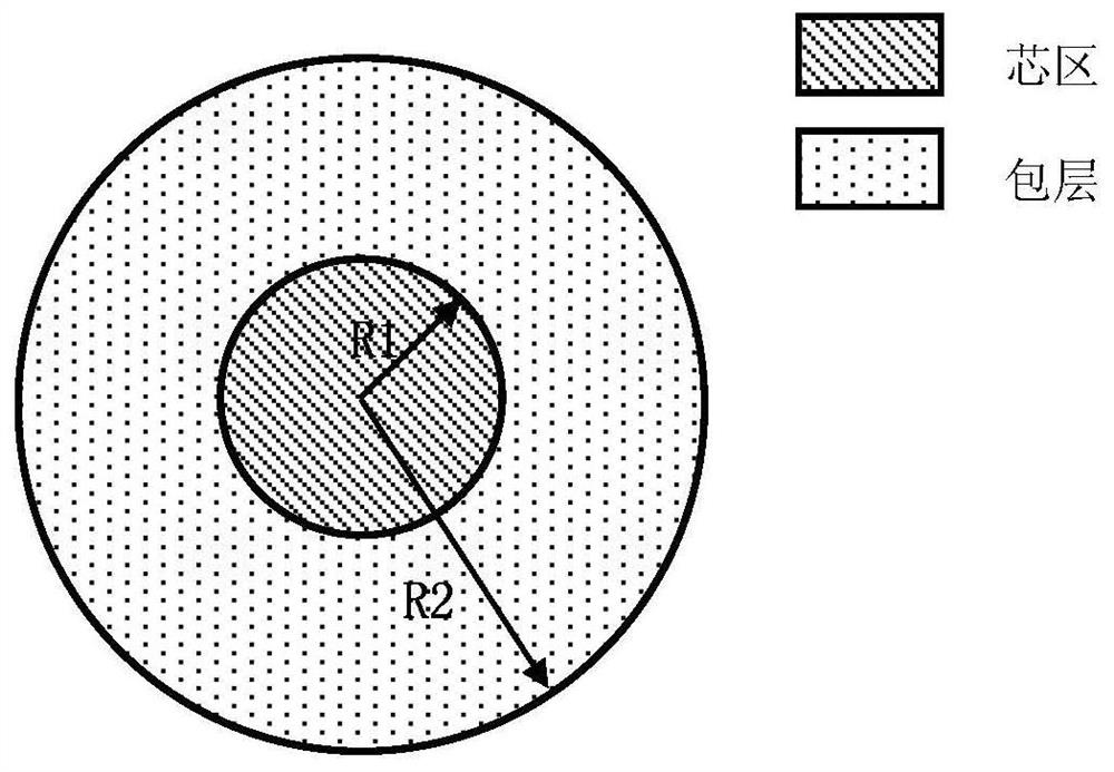
[0036] The cross-sectional shape is circular, and both the core material and the cladding material are chalcogenide materials. See Table 1 for the specific materials and refractive indices of the core and cladding (measured at a wavelength of 1550nm).

[0037] The core is Ge x1 Sb y1 Se z1 , 0x1 Sb y1 Se z1 The refractive index is 2.4~3.1; the cladding is Ge x2 Sb y2 S z2 , 0x2 Sb y2 S z2 The refractive index of 2.05 ~ 2.35.

[0038] Table 1

[0039] Core material Refractive index cladding material Refractive index Ge 12.5 Sb 5 Se 82.5

2.529 Ge 10 Sb 10 S 80

2.050 Ge 12.5 Sb 10 Se 77.5

2.610 Ge 15 Sb 20 S 65

2.1111 Ge 12.5 Sb 15 Se 72.5

2.702 Ge 21 Sb 11 S 68

2.1416 Ge 12.5 Sb 20 Se 67.5

2.803 Ge 23 Sb 10 S 67

2.1724 Ge 12.5 Sb 25 Se 62.5

2.933 Ge 23 Sb 12 S 65

2.211 Ge 28 Sb 12 Se 60

2.6505 Ge 23 Sb 17 S 60 ...

Embodiment 2

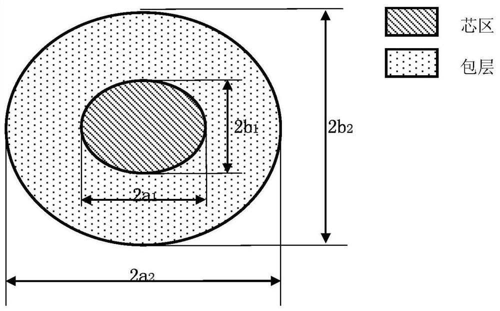
[0048] The core area and cladding material used are the same as in Example 1, and the core area adopts Ge 28 Sb 12 Se 60 , the refractive index is 2.6505; the cladding is made of Ge 23 Sb 10 S 67, The refractive index is 2.1724. The only difference is that its cross-sectional shape is oval, Figure 8 Shown this embodiment 2 cross-section is the dispersion flat curve of X, Y polarized light of elliptic time fundamental mode, from Figure 8 As can be seen in , light of different polarization states in the elliptical cross-section has little effect on the dispersion value.

Embodiment 3

[0050] The core material is a compound composed of two elements, and the cladding material is a compound composed of three elements. The specific materials and refractive indices (measured at a wavelength of 1550nm) of the core and cladding are shown in Table 2.

[0051] The core is As x1 Se y1 , 0x1 Se y1 The refractive index is 2.65-2.95; the cladding is Ge x2 As y2 Se z2 , 0x2 As y2 Se z2 The refractive index of 2.46 ~ 2.62.

[0052] Table 2

[0053] Core material Refractive index cladding material Refractive index As 40 Se 60


PUM

PropertyMeasurementUnit
refractive indexaaaaaaaaaa

Abstract

The invention discloses a broadband dispersion control fiber and a dispersion control method thereof. The broadband dispersion control fiber comprises a core region and a cladding. The cross-sectional shapes of the core region and the cladding are circular or elliptical. The core region and the cladding are arranged coaxially; and the refractive index of core region material is n1, and the refractive index of the cladding material is n2, 1.15<=n1 / n2<=1.5. Control parameters are few, bandwidth of a dispersion flat area is larger, and dispersion flat property is good; the core region and the cladding adopt chalcogenide material preferably, and have higher refractive index, so that higher non-linear refractive index is achieved; the broadband dispersion control fiber is high in chemical stability, is low in glass transition temperature, is easy to form and is simple to manufacture, has better infrared transmittance and is larger in transparent region; and the broadband dispersion control fiber is wide in application, such as a broadband light source: a super-continuum spectrum generator, a frequency comb generator and a mode-locked multi-wavelength light source, and a fiber laser: a wavelength tunable laser, an optical parametric oscillator and a femto-second laser.

Description

technical field [0001] The present invention relates to the field of optical fiber technology, and more specifically, to a broadband dispersion control optical fiber and a dispersion control method thereof. Background technique [0002] Dispersion refers to the phenomenon that when a beam of light pulses is transmitted in a waveguide, different frequencies of light propagate at different speeds, resulting in pulse broadening. Realization of dispersion control in optical fiber structure has always been the focus of people's research, because its dispersion control properties are the basis of many nonlinear applications. For example, achieving a broad-spectrum near-zero dispersion plateau can reduce the phase mismatch of interacting light waves, thereby enhancing the nonlinear efficiency. If the chromatic dispersion can be kept low in a very wide band, many nonlinear applications such as the manipulation of ultrashort pulses, the production of octave light sources (generation...

Claims


Application Information

Patent Timeline
Patent Type & Authority Patents(China)
IPC IPC(8): G02B6/02
CPCG02B6/02214
Inventor 张林张远航郭宇昊
Owner TIANJIN UNIV
Learn More