Working method of drawbench with cooling function for electric brush machining

A working method and wire drawing machine technology, which is applied to metal processing equipment, manufacturing tools, abrasive belt grinders, etc., can solve the problem that the accuracy and efficiency of wire drawing cannot be guaranteed at the same time, and the adjustment of the height of the workbench is prone to position deviation, which is difficult Problems such as processing workpieces wider than abrasive belts, etc., to improve processing quality and production efficiency, good cooling and cooling effect, and improve wire drawing efficiency

Inactive Publication Date: 2017-12-12
SUZHOU YONGBO ELECTRIC
View PDF7 Cites 1 Cited by
  • Summary
  • Abstract
  • Description
  • Claims
  • Application Information

AI Technical Summary

Problems solved by technology

[0004] 1. The operation is complicated, and the height of the workbench can only be adjusted manually. Therefore, it is very laborious to adjust the workbench for heavy workpieces, and the drawing accuracy and drawing efficiency cannot be guaranteed at the same time. At the same time, it is difficult to process wider than the abrasive belt. the workpiece;
[0005] 2. The workload of personnel is still very large, and the positioning accuracy of the workpiece is low, and the position deviation is prone to occur when the height of the workbench is adjusted;
[0006] 3. The work safety is poor. After increasing the drawing speed of the workpiece, it is likely to cause the temperature of the workbench to rise. If it cannot be cooled in time, it is easy to cause a fire;
[0007] 4. Since most of them are working in the open air, it is easy to cause dust to fall around the device during work, plus the fine debris generated by their own work, so the staff will inhale a large amount of harmful particles during long-term operations, which will seriously damage the equipment. to the life and health of staff

Method used


Image

  • Working method of drawbench with cooling function for electric brush machining

Examples


Embodiment 1

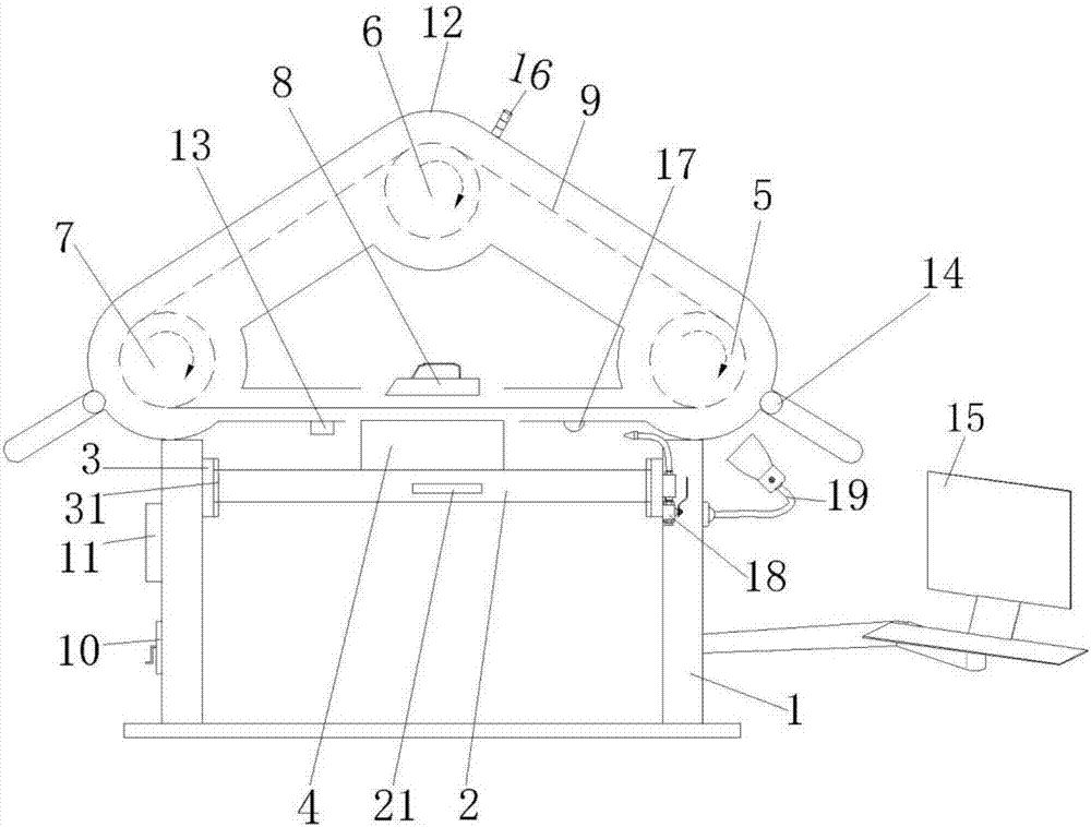
[0036] Such as figure 1 As shown, the working method of a wire drawing machine with cooling function for brush processing in this embodiment, the specific working steps are as follows:

[0037] (1), first place the workpiece 4 in the middle of the workbench 2, and turn on the LED light 19 on one side of the frame 1;

[0038] (2) Start the power supply, and the staff sets the corresponding drum speed on the control panel 11 according to the material and size of the workpiece 4, and turns on the motor;

[0039] (3), the first drum 5, the second drum 6 and the third drum 7 drive the sandpaper belt 9 to run under the drive of the motor;

[0040] (4) The staff manually rotates the handle 10 or electrically adjusts the height of the workbench 2 to an appropriate position through the control panel 11, and judges the exact height of the workbench 2 through the laser distance measurement of the laser head 17 connected to the display 15;

[0041] (5) The staff performs wire drawing wo...


PUM


Abstract

The invention discloses a working method of a drawbench with a cooling function for electric brush machining, and relates to the technical field of refrigeration motor production and machining. A worker rotates a crank with hands, or the height of a workbench is electrically adjusted through a control panel to the appropriate position, a laser head connected with a displayer carries out laser ranging to judge the accurate height of the workbench, and the worker presses a hand pressing plate for drawing work of the surface of a workpiece; if the width of the workpiece is larger than that of an abrasive paper belt, the worker pushes and pulls the workbench through a handle, and therefore whole drawing work is completed; after the drawbench works for a period of time, the worker starts a waste removing mechanism to concentrate dust particles in a machine cover, and a rotatable cooling mechanism is started to wash and cool the surface of the workbench. According to the working method, operation of the worker is simple, drawing precision and efficiency are greatly improved, positioning precision is high, height adjustment of the workbench is precise, and the convenient cooling and dust removing functions are achieved.

Description

technical field [0001] The invention relates to the technical field of production and processing of refrigeration motors, in particular to a working method of a wire drawing machine with cooling function for brush processing. Background technique [0002] The triangular wire drawing machine is suitable for surface drawing treatment of various planes such as metal, rubber sheet, wood board, etc. All flat materials that require silk lines on the surface of the workpiece can be completed by this equipment, so its application range is very wide; after wire drawing treatment , the surface texture of the workpiece presents a clear straight hairline pattern, the surface of the workpiece is flat and smooth, the visual effect is good, and the workpiece is full of aesthetic feeling, which makes the workpiece more high-grade; especially after wire drawing and oxidation treatment, the product is more competitive in the market. With the rapid development of the national economy and the...

Claims


Application Information

Patent Timeline
Patent Type & Authority Applications(China)
IPC IPC(8): B24B21/00B24B21/18B24B55/02B24B55/00B24B55/08
CPCB24B21/006B24B21/18B24B55/00B24B55/02B24B55/08
Inventor 陆健
Owner SUZHOU YONGBO ELECTRIC
Why Eureka
Try Eureka