Method and device for measuring refractive index of broadband differential confocal infrared lens element

A differential confocal, measuring device technology, used in refractive power measurement, testing optical performance and other directions, can solve the problems of complex measurement process, inability to directly measure the refractive index of lens elements, low precision, etc., to achieve high measurement accuracy and measurement process. Convenient, focused beam with no dispersion effect

Active Publication Date: 2017-12-12
BEIJING INSTITUTE OF TECHNOLOGYGY
View PDF7 Cites 17 Cited by
  • Summary
  • Abstract
  • Description
  • Claims
  • Application Information

AI Technical Summary

Problems solved by technology

[0013] The purpose of the present invention is to overcome the defects that the existing refractive index measurement technology cannot directly measure the refractive index of the lens element, the measurement process is complicated, and the precision is low, and prop

Method used


Image

  • Method and device for measuring refractive index of broadband differential confocal infrared lens element
  • Method and device for measuring refractive index of broadband differential confocal infrared lens element
  • Method and device for measuring refractive index of broadband differential confocal infrared lens element

Examples


Embodiment 1

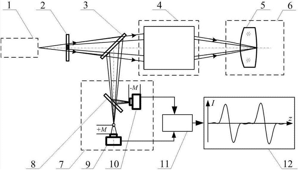
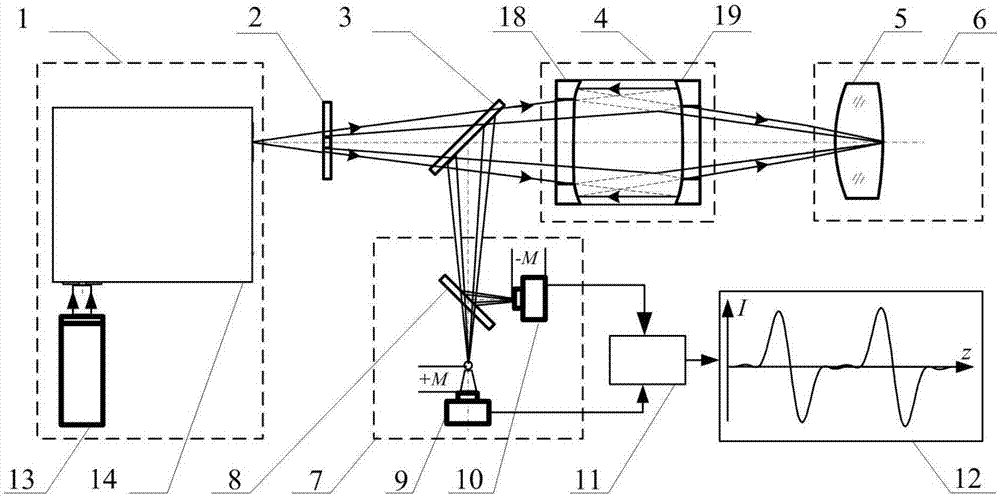
[0048] The embodiment of the present invention is based on Figure 4 The wide-band differential confocal infrared lens element refractive index measurement device shown is composed of a silicon carbon black body light source 13 and a grating monochromator 14 figure 1 Broadband point source system in 1. Composed of attitude adjustment system 20 and axial drive system 21 figure 1 In the adjustment and drive system 6, the first broadband beam splitting system 3 and the second broadband beam splitting system 8 use broadband beam splitters, and the first detector 9 and the second detector 10 use photodetectors.

[0049] Such as Figure 4 As shown, the device for measuring the refractive index of a wide-band differential confocal infrared lens element includes: a silicon carbon blackbody light source 13, a grating monochromator 14 positioned in the outgoing direction of the silicon carbon blackbody light source 13, and a light source positioned in the outgoing direction of the gra...

Embodiment 2

[0066] Such as Figure 5 In the wide-band differential confocal infrared lens element refractive index measurement device shown, the device is composed of a silicon carbon blackbody light source 13 and a filter group monochromator 14 figure 1 The wide-band point light source system 1 is composed of a five-dimensional adjustment frame as the attitude adjustment system 20 and an air bearing guide rail as the axial drive system 21 figure 1 Adjustment and drive system in 6.

[0067] All the other measuring methods are the same as in Example 1.


PUM


Abstract

The invention relates to a method and a device for measuring a refractive index of a broadband differential confocal infrared lens element and belongs to the technical field of precise optical measurement. The method disclosed by the invention comprises the following steps: generating a specified wavelength lighting point light source through a wavelength gating system by adopting a blackbody source; performing tomographic focus fixing on vertexes of the front and rear surfaces of a measured lens by utilizing a differential confocal light path, and measuring to obtain the optical thickness of the measured lens; and calculating to obtain the refractive index of the lens element by a ray tracing algorithm, thereby realizing high-precision non-contact measurement of the refractive index of the infrared lens element in a visible-to-infrared broadband range under any wavelength condition. According to the method disclosed by the invention, the measured lens does not need to be subjected to destructive sampling, nondestructive direct measurement of the refractive index of the infrared lens element in the visible-to-infrared range under any wavelength condition is realized for the first time, and the method has the advantages of being convenient in measurement process, high in measurement accuracy and high in environmental disturbance resistance and can provide a brand new effective technical approach for detecting the refractive index of the lens element.

Description

technical field [0001] The invention belongs to the technical field of optical precision measurement, which combines the technology of point light source generation at any wavelength in the visible to infrared wide band, differential confocal tomography fixed focus technology and ray tracing refractive index calculation algorithm, and relates to a wide band differential confocal The method and device for measuring the refractive index of an infrared lens element can be used for high-precision direct measurement of the refractive index of a lens element under the condition of any wavelength in the visible to infrared band. technical background [0002] Lens is a basic component in the field of visible and infrared optics. It is widely used in navigation control, wide-spectrum observation, laser processing and weapon systems. As its key parameter, its refractive index is an important basis for analyzing lens performance and ensuring the quality of optical systems. Accurate tes...

Claims


Application Information

Patent Timeline
IPC IPC(8): G01M11/02
CPCG01M11/0228
Inventor 王允赵维谦邱丽荣
Owner BEIJING INSTITUTE OF TECHNOLOGYGY
Why Eureka
Try Eureka