Coal-fired boiler flue gas desulphurization and denitrification device

A coal-fired boiler and flue gas technology, applied in the field of coal-fired boiler flue gas desulfurization and denitrification equipment, flue gas desulfurization and denitrification equipment, can solve the problems of low removal efficiency of compound pollutants, complex preparation of lime slurry, inconvenient transportation and storage, etc. , to achieve the effects of small footprint, easy maintenance, and low investment and operation costs

Inactive Publication Date: 2017-12-15
无锡市曜通环保机械有限公司
0 Cites 0 Cited by

AI-Extracted Technical Summary

Problems solved by technology

[0003] (1) The denitrification process mainly uses ammonia water as a reducing agent to react with nitrogen oxides in the flue gas; its disadvantage is that ammonia water and liquid ammonia are dangerous goods and are not convenient for transportation and storage
[0004] (2) The semi-dry desulfurization method is to spray lime slurry into the reactor through nozzles or rotary sprayers to form droplets with smaller particle sizes, so that SO...

Abstract

The invention relates to a coal-fired boiler flue gas desulphurization and denitrification device, comprising a coal-fired boiler, an on-line flue gas monitoring and control device, a bag-type dust collector, a fan, an adsorptive reactor, a water bath type ammonia gasifier and a wet electro-static precipitator; the device is characterized in that the coal-fired boiler is connected with the on-line flue gas monitoring and control device, the bag-type dust collector, the fan, the adsorptive reactor, the water bath type ammonia gasifier and the wet electro-static precipitator by pipelines; the on-line flue gas monitoring and control device is connected with a frequency-variable rotary feeder; an electronic screw scale is connected with the upper part of the frequency-variable rotary feeder and is also connected with an unloader. The coal-fired boiler flue gas desulphurization and denitrification device can be used for removing pollutants such as SO2, NOx, mercury, dioxin and smoke in coal-fired boiler flue gas; the fine particulate matters and aerosol in the flue gas are removed by means of the wet electro-static precipitator, and the removal rates of the fine particulate matters and the aerosol reach up to 99-99.99%, so that the combined pollutants such as the fine particulate matters and SO3 acid mist can be efficiently removed; therefore, up-to-standard emission of the flue gas is realized, and the environmental pollution is reduced.

Application Domain

Technology Topic

Flue-gas desulfurizationCoal fired +14

Image

  • Coal-fired boiler flue gas desulphurization and denitrification device
  • Coal-fired boiler flue gas desulphurization and denitrification device
  • Coal-fired boiler flue gas desulphurization and denitrification device

Examples

  • Experimental program(1)

Example Embodiment

[0013] The present invention will be further explained below in conjunction with the drawings.
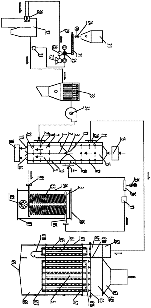
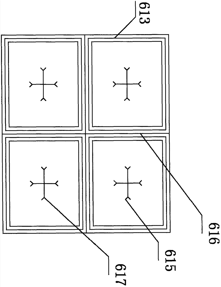
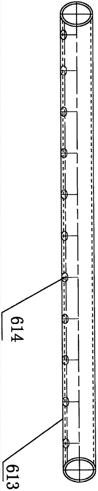
[0014] Such as figure 1 , figure 2 , image 3 As shown, the present invention is a coal-fired boiler flue gas desulfurization and denitrification device, including coal-fired boiler 32, flue gas online monitoring and control device 31, bag filter 33, fan 34, adsorption reactor 1, water bath ammonia gasification 8. Wet electrostatic precipitator 6, characterized in that: the coal-fired boiler 32 is connected to the flue gas online monitoring and control device 31, the bag filter 33, the fan 34, the adsorption reactor 1, the water bath ammonia vaporizer 8 through the pipeline , Wet electrostatic precipitator 6, the flue gas online monitoring and control device 31 is connected to a frequency conversion rotary feeder 26, the upper part of the frequency conversion rotary feeder 26 is connected to an electronic screw scale 25, and the electronic screw scale 25 is connected to a discharger 24, a discharger 24 is connected to the urea particle silo 23, and the mixing generator 28 is connected below the frequency conversion rotary feeder 26. The mixing generator 28 is connected to a high-pressure Roots blower 27, and the other is connected to the urea particle injection port 30 through a urea particle injection pipe 29. The injection port 30 is located above the side wall of the furnace of the coal-fired boiler 32. The adsorption reactor 1 is a composite-layer two-stage cross-flow moving bed. The cross-section of the adsorption reactor 1 is rectangular and the whole is approximately cuboid. The reactor 1 is composed of a denitration section and a desulfurization section. The denitration section includes a denitration section gas chamber 11, a denitration zone 15 and a denitration section gas sub-chamber 12, and the desulfurization section includes a desulfurization section gas chamber 10 and a desulfurization zone. 22 and the desulfurization section gas chamber 9, the denitrification zone 15 and the desulfurization zone 22 are connected through the feed channel 3 arranged between the two sections, the denitration section gas chamber 12 and the desulfurization section gas collection chamber 10 A flue gas and ammonia mixing chamber 19 is provided. The desulfurization section gas sub-chamber 9 is connected to a flue gas inlet 21, the flue gas inlet 21 is connected to the outlet of the fan 34, and the denitration section gas collection chamber 11 is connected to a flue gas outlet 20 The gas collection chamber 10 of the desulfurization section communicates with the gas sub-chamber 12 of the denitration section through a flue gas ammonia mixing chamber 19, and the flue gas ammonia mixing chamber 19 communicates with an ammonia gas inlet 4. An active coke stratified grid 2 is arranged in the zone 22, and the desulfurization zone 22 is divided into a front active coke layer 7 and a rear active coke layer 5, and the lower part of the front active coke layer 7 and the rear active coke layer 5 are respectively arranged corresponding to the front The discharge port 13 and the rear discharge port 14. The front discharge port 13 and the rear discharge port 14 control the different discharge flow of activated coke through valves, so that the activated coke particles are in the front active coke layer 7 and the desulfurization zone. The downward moving speed and residence time of the rear active coke layer 5 are different. The front discharge port 13 and the rear discharge port 14 are connected to the lower mixing silo 18, and a function is provided between the denitration section and the desulfurization section of the adsorption reactor 1 In the cleaning channel 17 for cleaning the active coke in the desulfurization zone 22 and the denitration zone 15, an adsorption reactor storage tank 16 is arranged above the adsorption reactor 1, and the water bath ammonia vaporizer 8 includes a cylinder 84. Coil type heat exchange tube 83, water-bath ammonia vaporizer inlet pipe 81 and water-bath ammonia vaporizer outlet pipe 85, the lower part of the cylinder 84 is provided with an electric heater 82, and the lower end of the left side of the cylinder 84 is provided There is a water-bath ammonia vaporizer inlet pipe 81, the upper right side of the cylinder 84 is provided with a water-bath ammonia vaporizer outlet pipe 85, four sets of plates The tubular heat exchange tube 83 is evenly installed in the cylinder 84, the top of the cylinder 84 is equipped with an upper head 86, the bottom of the cylinder 84 is equipped with a lower head 87, the lower head 87 is a flat bottom plate, and a water bath ammonia vaporizer The outlet pipe 85 is connected to the inlet of the ammonia buffer tank 37, the outlet of the ammonia buffer tank 37 is connected to the ammonia/air mixer 36, the ammonia/air mixer 36 is connected to the dilution ammonia fan 35, and the other is connected to the ammonia inlet 4, the flue gas outlet 20 is connected to the air inlet 62 of the wet electric precipitator 6 through a pipe. The wet electric precipitator 6 includes a housing 61 with a cavity inside, and the housing 61 is provided with an air inlet 62 , The air outlet 63 and the ash hopper 68. The ash hopper 68 is located at the bottom of the casing 61. The casing 61 is provided with an anode plate 64, a cathode line 65, a washing spray system 66 and a dust removal spray system 67, and the air inlet 62 and the outlet The air port 63 is located at the top of the housing 61. The housing 61 is provided with an airflow partition plate 610. The airflow partition plate 610 divides the housing 61 into an adjacent first cavity 611 and a second cavity 612. The cavity 611 is in communication with the air inlet 62, the second cavity 612 is in communication with the air outlet 63, the bottoms of the first cavity 611 and the second cavity 612 are in communication with each other, and a gas baffle 618 is provided. The first cavity 611 and the second cavity 612 are provided with at least one row of anode plates 64 with a square cross section and channels. The cathode wire 65 is suspended from the center of the channel of the anode plate 64, and the flushing spray The system 66 is located at a position 0.2m~0.4m above the anode plate 64, the dust removal spray system 67 is located on the top of the anode plate 64 of the second cavity 612, and the dust removal spray system 67 is a multi-row stainless steel pipe welding. Multiple rows and interconnected closed loop spray pipes 613, the spray pipe 613 is closely attached to the top of the anode plate 64, the spray pipe 613 is distributed with shallow taper spray holes 614, the cathode wire 65 is thin The cross shape of steel material, the ends of which are provided with zigzag discharge plates 615, the gas deflector 618 is located between the first cavity 611 and the second cavity 612, and the ash hopper 68 is provided with a return port 69. The two ends of the pole wire 65 are respectively connected to the cathode suspension frame 616 and the cathode fixing frame 617, the cathode suspension frame 616 is located at the top of the cathode wire 65, and the cathode fixing frame 617 is located at the bottom end of the cathode wire 65.
[0015] The working process of the present invention: 1000t/h coal-fired boiler 32, flue gas volume 180×10 4 m 3 /h, flue gas temperature 120~190℃, SO 2 The concentration of 4200~4500mg/Nm 3 ,NOx concentration 700~900mg/Nm 3 , Dust concentration 20g/Nm 3 , The oxygen content is between 5% and 8%;
[0016] Urea granule silo 23, unloader 24, electronic screw scale 25, frequency conversion rotary feeder 26, high-pressure Roots blower 27, mixing generator 28, urea particle injection pipe 29, urea particle injection port 30, etc. Particle injection device; flue gas online monitoring and control device 31 detects the amount of flue gas and the amount of NOx produced in coal-fired boiler 32, and feeds it back to the PLC control system. The PLC control system calculates the consumption of urea, which is weighed by the electronic screw scale 25 After re-measurement, the conveying volume is adjusted by changing the speed according to the working conditions through the frequency conversion rotary feeder 26. The conveying volume is sent to the mixing generator 28, and the wind from the high-pressure Roots blower 27 will fall into the mixing generator 28 The urea particles are sent to the urea particle injection port 30 through the urea particle injection pipe 29 into the furnace of the coal-fired boiler 32. In the furnace of the coal-fired boiler 32, the urea particles and the nitrogen oxides in the flue gas undergo a chemical reaction:
[0017] 2CO(NH 2 ) 2 +4NO+O 2 = 4N 2 +4H 2 O+2CO 2
[0018] 4CO(NH 2 ) 2 +4NO 2 = 6N 2 +8H 2 O+2CO 2
[0019] NOx is reduced to N in the furnace 2 And water
[0020] After the pre-denitration treatment, the flue gas of the coal-fired boiler 32 enters the bag filter 33 through the negative pressure of the fan 34 to remove dust from the dust-containing flue gas of the coal-fired boiler 32.
[0021] To prevent dust from entering the adsorption reactor 1 to cause blockage, the flue gas of the coal-fired boiler 32 passing through the bag filter 33 enters the adsorption reactor 1 by the action of the fan 34;
[0022] The flue gas enters the desulfurization section of the adsorption reactor 1 from the flue gas inlet 21 of the adsorption reactor 1, and contacts with the active coke falling from the top to the cross flow to remove the SO in the flue gas 2 , Dioxins and Mercury, the flue gas passes through the desulfurization section and the ammonia gas introduced from the ammonia gas inlet 4 is mixed in the flue gas ammonia mixing chamber 19, and flows upwards and crosses the denitration section to achieve flue gas denitration. The gas is discharged from the flue gas outlet 20 of the adsorption reactor 1;
[0023] The liquid ammonia is transported by tanker to the liquid ammonia storage tank, and the output liquid ammonia is turned into ammonia gas through the water-bath ammonia vaporizer 8, which is sent to the ammonia gas buffer tank 37 for standby; the ammonia gas in the ammonia gas buffer tank 37 After being decompressed, it is sent to the ammonia/air mixer 36, mixed with the air from the diluted ammonia fan 35, enters the ammonia inlet 4 through the pipeline, and then enters the adsorption reactor 1, when the flue gas flows through the adsorption reactor At 1 o'clock, a chemical reaction occurs and NOx is selectively reduced:
[0024] 4NH 3 +4NO+O 2 →4N 2 +6H 2 O
[0025] 8NH 3 +6NO 2 →7N 2 +12H 2 O
[0026] NOx is reduced to N in adsorption reactor 1 2 And water
[0027] The flue gas enters the wet electrostatic precipitator 6 from top to bottom, and the flue gas enters the first cavity 611 from the air inlet 62. The cathode line 65 of the first cavity 611 and the second cavity 612 is supplied with high voltage. The cathode wires 65 in the channels of the first cavity 611 and the second cavity 612 generate electric discharges to form electric field channels, so that the gas passing through the electric field channels of the first cavity 611 is charged and moves toward the anode plate 64 under the action of the electric field force. It is deposited on the anode plate 64 to achieve the effect of primary removal of fine particles and aerosols; the flue gas after the primary removal is guided by the gas deflector 618 and uniformly enters the second cavity 612, the second cavity 612 The inner anode plate 64 has a dust removal spray system 67 on the top of the anode plate 64 to spray the anode plate 64, and a water film is formed on the anode plate 64 to purify and collect the charged dust. The continuous flow of water film simultaneously takes the collected dust The bottom ash hopper 68 is discharged from the return port 69. The flushing spray system 66 is set above the anode plate 64 to intermittently flush the anode plate 64 and the cathode line 65 of the first cavity 611 and the second cavity 612. Finally, the dust-purified gas is discharged from the air outlet 63; the flue gas passes through the wet electrostatic precipitator 6 to remove fine particles and aerosols with an efficiency of 99-99.99%, which realizes the efficient removal of complex pollutants in the flue gas. In addition, environmental pollution is reduced, and the ever-increasing air emission standards are met.

PUM

no PUM

Description & Claims & Application Information

We can also present the details of the Description, Claims and Application information to help users get a comprehensive understanding of the technical details of the patent, such as background art, summary of invention, brief description of drawings, description of embodiments, and other original content. On the other hand, users can also determine the specific scope of protection of the technology through the list of claims; as well as understand the changes in the life cycle of the technology with the presentation of the patent timeline. Login to view more.

Similar technology patents

Classification and recommendation of technical efficacy words

  • Improve denitrification efficiency
  • Improve desulfurization efficiency

Ammonia flue gas desulfuration and denitration combined process and device

InactiveCN103041678APromote denitrificationImprove denitrification efficiencyUsing liquid separation agentPerfluorocarbons/hydrofluorocarbons captureFomesChemistry
Owner:ZHEJIANG TIANLAN ENVIRONMENTAL PROTECTION TECH

Slag diluent for molten iron desulphurization slag

InactiveCN101338348AImprove desulfurization efficiencyEnhance the effect of thin slagSodium carbonateSlag
Owner:WUHAN IRON & STEEL (GROUP) CORP +1
Why Eureka
Try Eureka