Low power consumption CO cryogenic separation system and separation method thereof

A technology of cryogenic separation and low power consumption, applied in cold process separation, refrigeration and liquefaction, liquefaction, etc., can solve the problem of long startup time, large amount of emptying during startup, power consumption and investment of analytical gas compressor and CO cycle compressor It can reduce power consumption and investment, shorten start-up time, good economic benefits and environmental protection benefits

Active Publication Date: 2017-12-19
四川蜀道装备科技股份有限公司
View PDF12 Cites 0 Cited by
  • Summary
  • Abstract
  • Description
  • Claims
  • Application Information

AI Technical Summary

Problems solved by technology

The power consumption and investment of the analytical gas compressor and the CO cycle compressor of this process are large, and the start-up time of the device is long, and the amount of venting during the start-up phase is large

Method used


Image

  • Low power consumption CO cryogenic separation system and separation method thereof
  • Low power consumption CO cryogenic separation system and separation method thereof
  • Low power consumption CO cryogenic separation system and separation method thereof

Examples


Embodiment 1

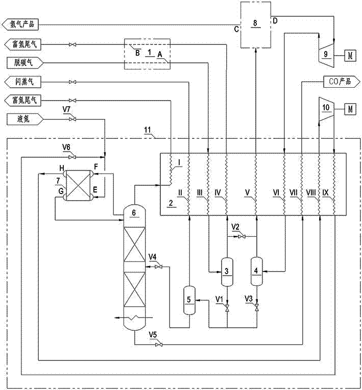
[0036] Example one: such as figure 1 As shown, a low-power CO cryogenic separation system includes a decarburization gas purification unit, a cryogenic separation unit, a PSA hydrogen production unit, a desorption gas compressor unit, and a circulating compressor unit;

[0037] In this embodiment, the decarburization gas purification unit 1 includes a decarburization gas flow channel A and a regeneration gas flow channel B. The outlet of the decarburization gas flow channel A is connected to the inlet of the plate heat exchanger 2 flow channel III, and the regeneration gas flow channel The inlet of B is connected with the outlet of flow channel IV of plate heat exchanger 2;

[0038] In this embodiment, the cryogenic separation unit 11 includes a plate heat exchanger 2, a purified gas cryogenic separator 3, a desorption gas cryogenic separator 4, a cryogenic flash tank 5, a rectification tower 6 and a tower top condenser 7. The outlet of the flow channel III of the plate heat exchan...

Embodiment 2

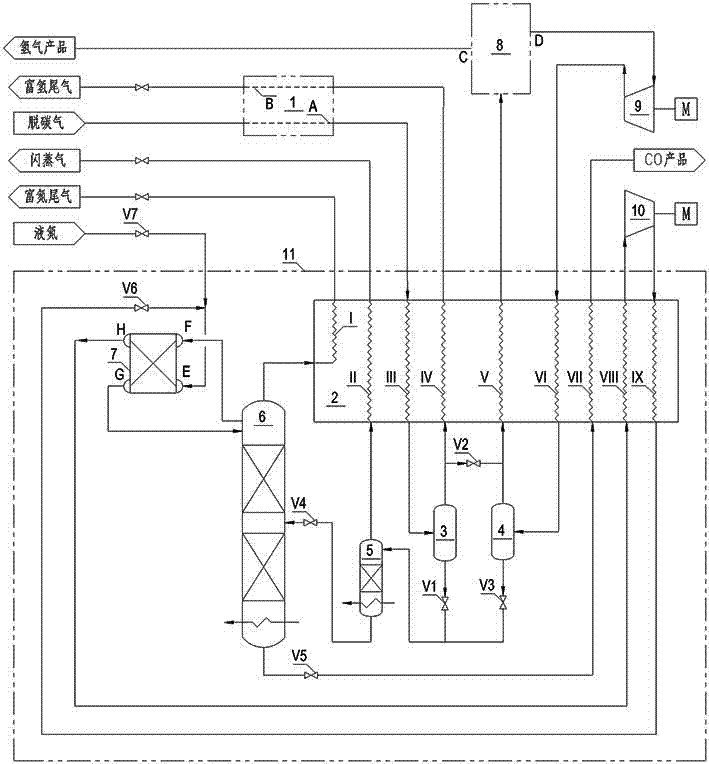
[0053] Example 2: Such as figure 2 As shown, the difference between this embodiment and Embodiment 1 is that the low-temperature flash tank 5 adopts an evaporative stripper, thereby appropriately increasing the recovery rate of CO and hydrogen.

Embodiment 3

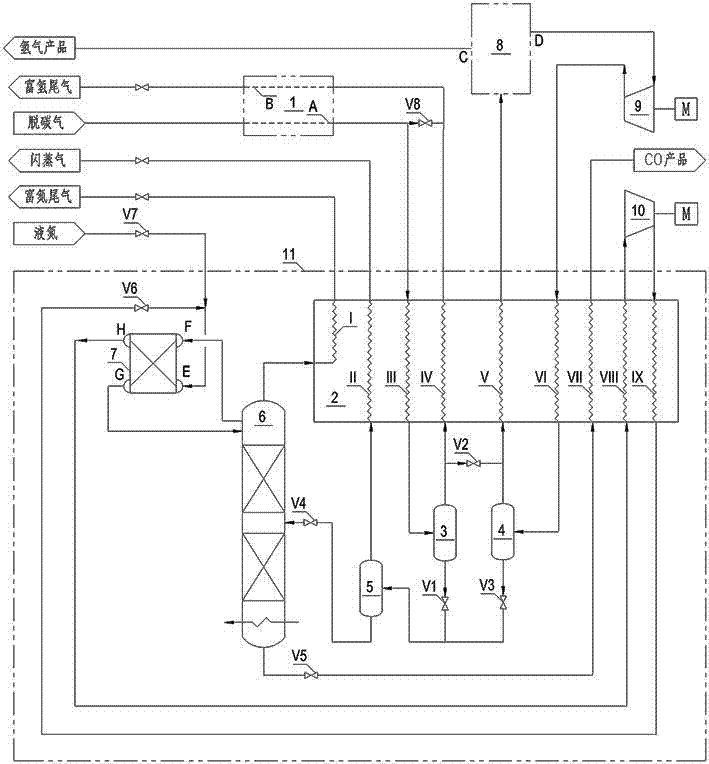
[0054] Example 3: Such as image 3 As shown, the difference between this embodiment and Embodiment 1 lies in that a bypass line and valve V8 are added to the outlet of the decarburization gas flow channel A of the decarburization gas purification unit 1 to the inlet of the regeneration gas flow channel B for decarburization gas Regeneration gas is used to start or supplement the purification unit 1.


PUM


Abstract

The invention discloses a low power consumption CO cryogenic separation system. The low power consumption CO cryogenic separation system comprises a decarburizing gas purification unit, a cryogenic separation unit, a PSA hydrogen production unit, a parse gas compressor unit and a recycle compressor unit. The invention further discloses a separation method of the low power consumption CO cryogenic separation system. The separation method has the process steps of decarburizing gas purification, condensing and separating dehydrogenation, operation of a rectifying tower, operation of a recycle compressor, PSA hydrogen production and operation of a parse gas compressor. The low power consumption CO cryogenic separation system and the separation method of the low power consumption CO cryogenic separation system have the beneficial effects that hydrogen-rich tail gas or purifying gas is adopted to serve as resurgent gas, and it is guaranteed that parse gas of the PSA hydrogen production unit does not contain water or CO2; by independently arranging a parse gas heat exchanging channel and a low temperature separator, the power consumption of the parse gas compressor is substantially lowered; a nitrogen gas recycle compressor is adopted for replacing a CO recycle compressor low in efficiency, the power consumption of the recycle compressor is lowered, the starting time of the device can also be shortened, and the venting amount in the starting stage is reduced; and the energy consumption is low, starting is fast, investment is saved, the emission is little, and good economic benefits and environment protection benefits are achieved.

Description

Technical field [0001] The invention relates to a low power consumption CO cryogenic separation system and a separation method thereof, and belongs to the field of cryogenic gas separation. Background technique [0002] CO is an important raw material gas for oxo synthesis. Almost all organic chemicals can be prepared from CO. However, the purity of raw material CO is very high during the production of ethylene glycol, acetic acid and dimethyl diamide. ( ≥98.5%). Cryogenic separation technology has mature technology, stable operation, large processing capacity, high product purity, and high yield. It is currently the preferred technology for CO separation. [0003] In order to improve economic efficiency, many coal-to-methanol or synthetic ammonia plants have undergone partial transformation to co-produce ethylene glycol. Compared with newly-built ethylene glycol plants, the equipment investment is low and the construction period is short. However, in view of the fact that the sy...

Claims


Application Information

Patent Timeline
Patent Type & Authority Applications(China)
IPC IPC(8): F25J3/02
CPCF25J3/0204F25J3/0295F25J2245/02F25J2205/04F25J3/0223F25J3/0261F25J2270/42F25J2270/12F25J2210/42F25J3/0257F25J2205/40F25J2200/70F25J2205/60F25J2200/72F25J2270/904F25J3/0252Y02C20/40
Inventor 曹卫华文向南
Owner 四川蜀道装备科技股份有限公司
Why Eureka
Try Eureka