Single-stage photovoltaic grid-connected micro inverter and control method thereof

A micro-inverter, single-stage technology, applied in the electrical field, can solve the problems of difficulty in increasing the power, increase the volume of the inverter, burn out the circuit, etc., and achieve the effect of reducing the voltage distortion rate

Inactive Publication Date: 2017-12-26
QINGDAO UNIV
View PDF3 Cites 12 Cited by
  • Summary
  • Abstract
  • Description
  • Claims
  • Application Information

AI Technical Summary

Problems solved by technology

[0002] Traditional photovoltaic grid-connected micro-inverters generally have the following three structural forms: the first is a non-isolated two-stage structure, that is, the front stage uses a non-isolated Boost circuit to boost the voltage, and the latter stage uses an H-bridge inverter. The circuit is relatively simple, but the disadvantage is that the output of the micro-inverter is not isolated from the battery board, which will bring safety hazards and its efficiency is low
The second is an isolated two-stage structure, that is, the front stage uses an isolated voltage or current-type half-bridge LLC circuit to boost the voltage, and the latter stage uses an H-bridge inverter. The advantage is that the output of the micro-inverter and the battery board realize electrical Isolation eliminates potential safety hazards, and its pre-stage circuit can realize soft switching through resonance. The efficiency of the pre-stage circuit is relatively high. The disadvantage is that the inverter is relatively large in size and high in cost. The pre-stage is a current-type half-bridge LLC. The circuit control is relatively complicated, and two inductors are required, which increases the size of the inverter; the front stage is a voltage-type half-bridge LLC circuit control is relatively complicated, and the upper and lower switch tubes of the bridge arm are easy to pass through and burn the circuit; the third is isolation Type single-stage structure, currently the primary side of the transformer generally adopts flyback type, interleaved flyback type or interleaved flyback active clamping circuit, and the secondary side of the transformer adopts power frequency inverter, that is, the electrical isolation can be realized by using the primary circuit It is also reversible and connected to the grid, which saves the H-bridge inverter circuit at the rear stage. For the flyback or interleaved flyback circuit, the advantage is that the circuit structure is simple and easy to control. The disadvantage is that the transformer is unidirectionally excited, and the magnetic core is easy to saturate. , the power is difficult to increase, the switching tube cannot realize soft switching, and the efficiency is relatively low; for the interleaved flyback active clamp circuit, the switching tube in the active clamping branch and the main switching tube are complementary conduction, and the resonance makes Both switch tubes realize zero-voltage soft switching, and reduce the withstand voltage of the switch tube, which improves the efficiency relatively. However, the existing transformer is unidirectionally excited, the magnetic core is easy to saturate, and the power is difficult to increase, which increases the control. Complexity
[0003] Combining the three structural forms of traditional photovoltaic micro-inverters, for isolated or non-isolated two-stage micro-inverters, the latter stage generally uses H-bridge inverters, and there are two switch tubes on the upper and lower sides of the bridge arm that are easy to pass through and burn out the circuit. , high control difficulty, low reliability, and low efficiency. In addition, the size of the micro-inverter increases after the cascading of the front and rear two stages, the reliability is reduced, and the efficiency is further reduced. At present, the isolated single-stage structure is gradually Replaced, but the isolated single-stage structure also has the problem of one-way excitation of the transformer

Method used


Image

  • Single-stage photovoltaic grid-connected micro inverter and control method thereof
  • Single-stage photovoltaic grid-connected micro inverter and control method thereof
  • Single-stage photovoltaic grid-connected micro inverter and control method thereof

Examples


Embodiment

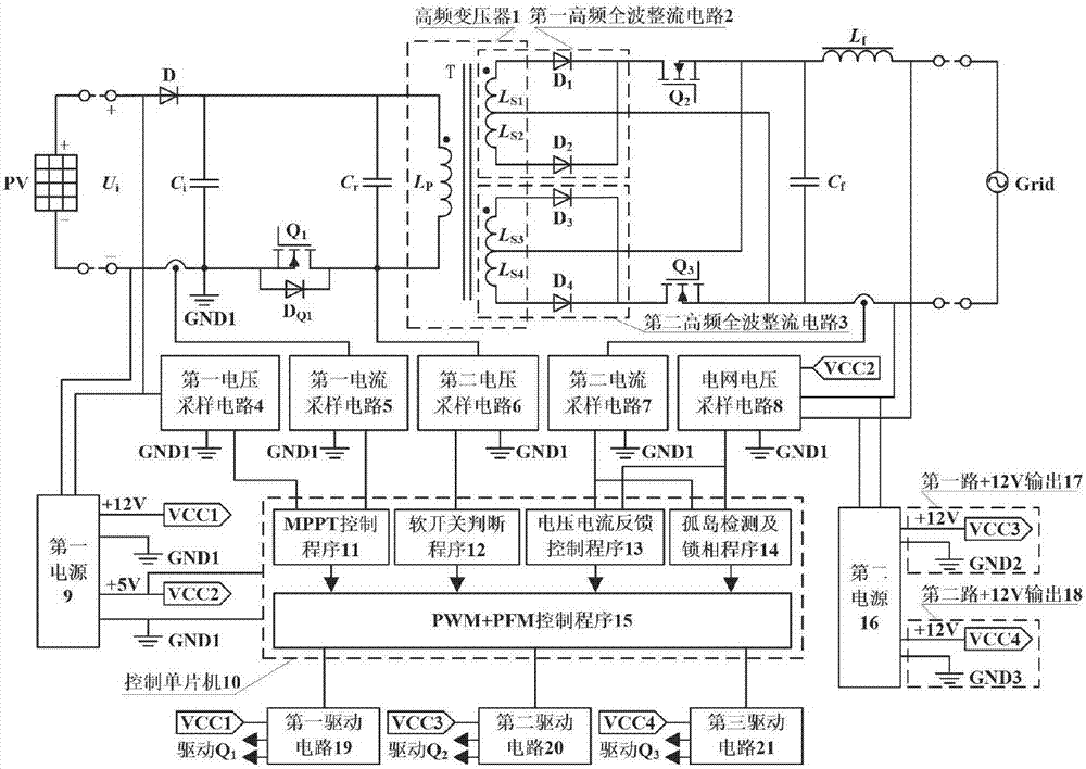
[0021] The main structure of the single-stage photovoltaic grid-connected micro-inverter in this embodiment includes a reverse blocking diode D, a capacitor C i , Resonant capacitance C r , the first switching tube Q 1 , Freewheeling diode D Q1 , high-frequency transformer 1, first high-frequency full-wave rectifier circuit 2, second high-frequency full-wave rectifier circuit 3, second switching tube Q 2 , the third switching tube Q 3 , filter capacitor C f , filter inductance L f , the first voltage sampling circuit 4, the first current sampling circuit 5, the second voltage sampling circuit 6, the second current sampling circuit 7, the grid voltage sampling circuit 8, the first power supply 9, the second power supply 16, the control microcontroller 10, the second A driving circuit 19, a second driving circuit 20 and a third driving circuit 21; the input voltage U i through the reverse blocking diode D and by the capacitor C i After filtering, it is used as the input o...


PUM


Abstract

The invention belongs to the technical field of electricity and relates to a single-stage photovoltaic grid-connected micro inverter and a control method thereof. The primary side of an isolation transformer achieves bidirectional excitation only through one switch tube, and the switch tube can achieve zero-voltage connection and disconnection and at the meantime transmit energy to the secondary side of the isolation transformer; the secondary side of the isolation transformer comprises two sets of high-frequency full-wave rectification circuits, which are controlled to output at a power frequency and then connected in parallel back to back, and is combined with modulation of a high-frequency switch tube of the primary side of the isolation transformer to form a pulse sequence changing by sinusoidal modulation rules and then filtered into grid-connectable power-frequency alternate current. The single-stage photovoltaic grid-connected micro inverter is simple in structure, small in size, low in cost and high in efficiency and reliability, and can be applied to other small grid-connected inverters besides photovoltaic grid-connected micro inverters; after island detection and phase lock programs are eliminated, the single-stage photovoltaic grid-connected micro inverter can be applied in a generalized mode to vehicle-mounted inverters, USB (universal serial bus) power sources, frequency converters and isolated boost DC-AC (direct current-alternate current) converters.

Description

Technical field: [0001] The invention belongs to the technical field of electricity, and relates to a grid-connected micro-inverter and a control method thereof, in particular to a novel high-efficiency single-stage photovoltaic grid-connected micro-inverter and a control method thereof for a single solar panel. Background technique: [0002] Traditional photovoltaic grid-connected micro-inverters generally have the following three structural forms: the first is a non-isolated two-stage structure, that is, the front stage uses a non-isolated Boost circuit to boost the voltage, and the latter stage uses an H-bridge inverter. The circuit is relatively simple, but the disadvantage is that the output of the micro-inverter is not isolated from the battery board, which will bring safety hazards, and its efficiency is low. The second is an isolated two-stage structure, that is, the front stage uses an isolated voltage or current-type half-bridge LLC circuit to boost the voltage, an...

Claims


Application Information

Patent Timeline
Patent Type & Authority Applications(China)
IPC IPC(8): H02M7/537H02M7/5375H02M7/5383H02J3/38
CPCH02J3/383H02M7/537H02M7/5375H02M7/5383H02J3/388H02M1/0058Y02E10/56
Inventor 王春芳赵永强郑再余
Owner QINGDAO UNIV
Why Eureka
Try Eureka