Enhanced cathodic arc source for arc plasma deposition

A cathodic arc source and plasma technology, which is applied in the direction of plasma, ion implantation plating, circuits, etc., can solve the problems of low plasma transmission efficiency, reduced carbon film deposition rate, and reduced transparency.

Active Publication Date: 2018-01-05
VEECO INSTR
View PDF7 Cites 6 Cited by
  • Summary
  • Abstract
  • Description
  • Claims
  • Application Information

AI Technical Summary

Problems solved by technology

Although metal, metal-compound, and DLC films have been synthesized, large particle filters suffer from two major drawbacks: (1) inefficient plasma transport, i.e. only a fraction of the initial plasma is actually used for film deposition, and (2) Large particles cannot be completel

Method used


Image

  • Enhanced cathodic arc source for arc plasma deposition
  • Enhanced cathodic arc source for arc plasma deposition
  • Enhanced cathodic arc source for arc plasma deposition

Examples


Embodiment Construction

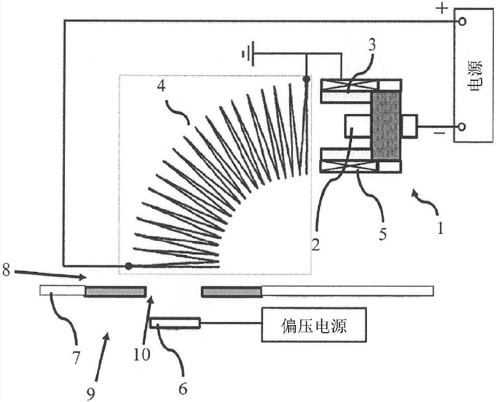
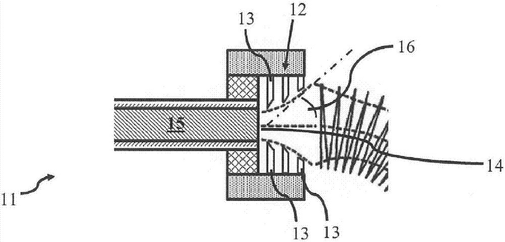
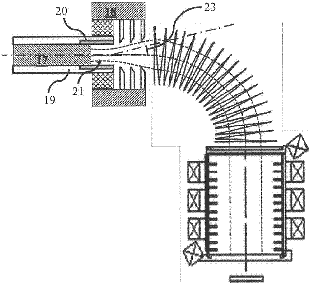
[0026] figure 1 is a schematic diagram illustrating a miniaturized Pulse Filter Cathode Arc (PFCA) source with an open architecture filter. Such as figure 1 As shown in , a miniaturized cathodic arc source 1 has a cathode 2 inside an anode 3 . The cathodic arc source 1 can be located close to the inlet of the filter 4, for example the surface of the cathode 2 is preferably positioned about 0.5 to 2 times the inner diameter of the filter coil relative to the inlet. The cathodic arc source 1 may also include a focusing or injection solenoid 5 to increase the output of plasma from the source to the filter. Filters may be formed from curved solenoidal coils with an open architecture, which typically have at least one of the following features: 1) Additional field injection or focusing coils located at the filter inlet to increase the flow of plasma from the source to the filter. , and 2) coil turns with a flattened cross-section to facilitate reflection of large particles off t...


PUM


Abstract

The invention provides an enhanced cathodic arc source for arc plasma deposition. An improved cathodic arc source and method of DLC film deposition with a carbon containing directional-jet plasma flowproduced inside of cylindrical graphite cavity with depth of the cavity approximately equal to the cathode diameter. The generated carbon plasma expands through the orifice into ambient vacuum resulting in plasma flow strong self-constriction. The method represents a repetitive process that includes two steps: the described above plasma generation/deposition step that alternates with a recovery step. This step provides periodical removal of excessive amount of carbon accumulated on the cavity wall by motion of the cathode rod inside of the cavity in direction of the orifice. The cathode rod protrudes above the orifice, and moves back to the initial cathode tip position. The said steps periodically can be reproduced until the film with target thickness is deposited. Technical advantages include the film hardness, density, and transparency improvement, high reproducibility, long duration operation, and particulate reduction.

Description

technical field [0001] The present invention relates generally to techniques for thin film deposition using cathodic arc plasma sources, and more particularly to techniques suitable for the repeatable deposition of ultrahard and / or ultradense, low defect carbon films. Background technique [0002] Improving wear and corrosion resistance as well as sliding behavior is an important consideration in the field of thin film technology. These applications represent a wide variety of difficult operating conditions, often co-existing, such as adhesive, abrasive and corrosive interactions with sliding counterparts and the surrounding media. Diamond-like carbon ("DLC") coatings appear to fulfill many of these needs as protective layers: DLC represents a high mechanically hard material characterized by high hardness and Young's modulus. Additionally, it exhibits only a weak adhesion affinity for metals and most other materials. It is inert to most aggressive agents and environments. ...

Claims


Application Information

Patent Timeline
IPC IPC(8): C23C14/32C23C14/06H05H1/34
CPCC23C14/0605C23C14/543C23C14/564H01J37/32055H01J37/32357H01J37/32568H01J37/32614H01J37/32633H01J37/3266C23C14/325H01J37/32623H01J37/32669C23C14/0611C23C14/243C23C14/542
Inventor 波里斯·L·宙斯维克多·卡纳罗尤里·尼古拉·叶夫图霍夫山迪普·柯里方兴杰
Owner VEECO INSTR
Why Eureka
Try Eureka