Turn-over driving device of vehicle-mounted flat-panel display

A flat-panel display and driving device technology, which is applied in the direction of transmission, transmission parts, gear transmission, etc., can solve the problem of the large thickness of the vehicle-mounted flat-panel display overturning driving device, not adapting to the application trend of the vehicle-mounted flat-panel display, and the high processing cost of the box 25. problem, to achieve the effect of strong impact resistance, easy processing, and reduced processing difficulty

Pending Publication Date: 2018-01-05
XIAMEN XINSHENYUE ELECTROMECHANICAL
View PDF9 Cites 5 Cited by
  • Summary
  • Abstract
  • Description
  • Claims
  • Application Information

AI Technical Summary

Problems solved by technology

[0004] There are following defects in the above-mentioned technical scheme: 1, on the casing 25, on two opposite sidewalls along the length direction, set up the first worm 4 (transverse input shaft) and the second worm wheel 7 (transverse output shaft) in parallel. Bearing holes, and a pair of longitudinal bearing holes of the second worm 6 are provided on the two opposite end walls perpendicular to the two shafts on the box body 25; these bearing holes on the box body 25 require high machining accuracy, and it is difficult for ge

Method used


Image

  • Turn-over driving device of vehicle-mounted flat-panel display
  • Turn-over driving device of vehicle-mounted flat-panel display
  • Turn-over driving device of vehicle-mounted flat-panel display

Examples


Embodiment Construction

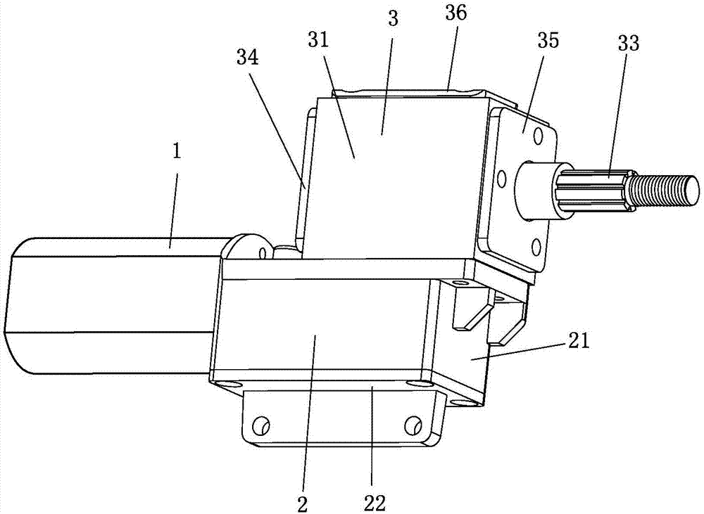
[0025] The three-dimensional structure of the vehicle-mounted flat panel display flip drive device of the present invention, such as figure 1 shown. It contains three main parts of motor 1, first reducer 2 and second reducer 3. In order to reduce the thickness of the entire display turning drive device, the motor 1 adopts a high-speed DC motor with a smaller diameter. In order to reduce the processing difficulty of the reducer case, the first reducer 2 and the second reducer 3 each have an independent case.

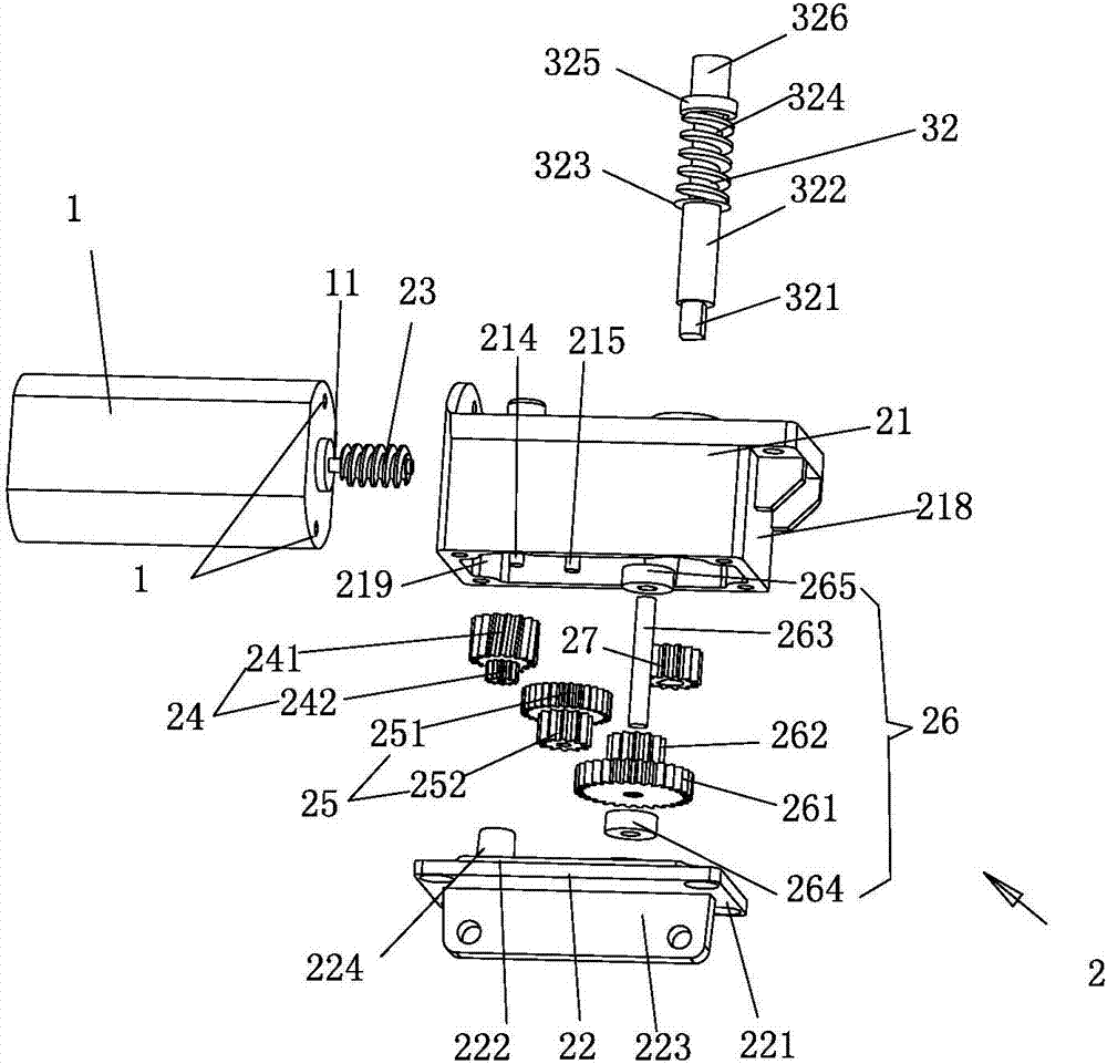
[0026] Please see figure 2 : the first speed reducer 2 comprises a first casing 21, a first case cover 22, a first worm 23, a first worm wheel 241, a first worm shaft 214, a first pinion 242, a first large gear 251, a second small The gear 252 , the first gear shaft 215 , the second large gear 261 , the third pinion 262 , the second gear shaft 263 , the first bearing 264 , the second bearing 265 and the output gear 27 . Wherein, the first small gear 242 , the first l...


PUM


Abstract

The invention discloses a turn-over driving device of a vehicle-mounted flat-panel display and relates to an electric driving device for changing the supporting state of a display. The turn-over driving device of the vehicle-mounted flat-panel display is provided with a motor and a deceleration mechanism which comprises two rectangular box bodies and two worm gears and two worms. A rotating shaftof the first worm in the deceleration mechanism is a transverse input shaft, a rotating shaft of the second worm gear in the deceleration mechanism is a transverse output shaft, and the two shafts areparallel to each other. Longitudinal bearings are mounted on a lower straight rod part and an upper straight rod part of the two sides of an arc surface thread part of the second worm correspondingly, transverse bearings are mounted on a left circular rod part and a right circular rod part of the two sides of a working part on the second worm gear correspondingly, wherein the working part is provided with a plurality of arc surface tooth grooves along the circumference surface, and the arc surface thread part of the second worm is engaged with the arc surface tooth grooves of the second wormgear. The deceleration mechanism is provided with the two rectangular box bodies, the first worm and the first worm gear are mounted in the first box body, the second worm, the two longitudinal bearings of the second worm, the second worm gear and the two transverse bearings of the second worm gear are mounted in the second box body, and thus machining and production are facilitated.

Description

technical field [0001] The invention relates to an electric driving device for changing the supporting state of a display. Background technique [0002] The vehicle-mounted flat-panel display is usually installed at the position corresponding to the top of the compartment and the aisle. In order not to hinder the passengers from walking, the flat-panel display is usually turned upside down and placed in a horizontal state against the top of the compartment. When in use, the flat-panel display is turned upside down and turned into an upright state, which is convenient for passengers to watch programs. The flipping of the flat panel display is realized by an electric flipping drive. The vehicle-mounted flat-panel display must resist the impact of bumps and sudden brakes during vehicle driving, and the output shaft of its tilting drive device is required to withstand large impacts and effectively eliminate free clearance. In vehicle conditions, the size of the flip driving de...

Claims


Application Information

Patent Timeline
IPC IPC(8): F16H1/22F16H57/039F16H57/022F16H57/023B60R11/02
Inventor 巫华志
Owner XIAMEN XINSHENYUE ELECTROMECHANICAL
Why Eureka
Try Eureka