
Pyrolysis reaction system

A pyrolysis reaction and pyrolysis reactor technology, applied in the field of coal chemical industry, can solve the problems of large energy waste, low calorific value of pyrolysis gas, large load of gas processing system, etc., and achieves reduction of thermal energy loss, good pyrolysis effect, Thermally efficient effect

Active Publication Date: 2018-01-09
CHNA ENERGY INVESTMENT CORP LTD +1
View PDF3 Cites 0 Cited by
  • Summary
  • Abstract
  • Description
  • Claims
  • Application Information

AI Technical Summary

Problems solved by technology

[0004] However, in the prior art, the pyrolysis process of coal usually adopts the gas heat carrier method, and its disadvantages are: (1) the calorific value of the pyrolysis gas is low; (2) the subsequent gas treatment system has a large load, especially the gas For heat carrier technology, if the processing capacity is 500,000 tons / year, the inner diameter of the air outlet of the dryer needs to reach about 3.1m. If the processing capacity reaches 1 million tons / year, subsequent large pipeline layout and industrial equipment processing are quite difficult
Moreover, the high-temperature semi-coke after pyrolysis cannot be utilized, which results in a great waste of energy.
As for the pyrolysis of liquefied residues, due to the high viscosity of liquefied residues, the liquefied residues must pass through the softening point when the temperature rises to the pyrolysis process. If the treatment is not done properly, the softened liquefied residues will often lead to sticking, caking, etc. , or even block the entire device, causing many operational failures

Method used


Image

  • Pyrolysis reaction system
  • Pyrolysis reaction system
  • Pyrolysis reaction system

Examples


Embodiment 1

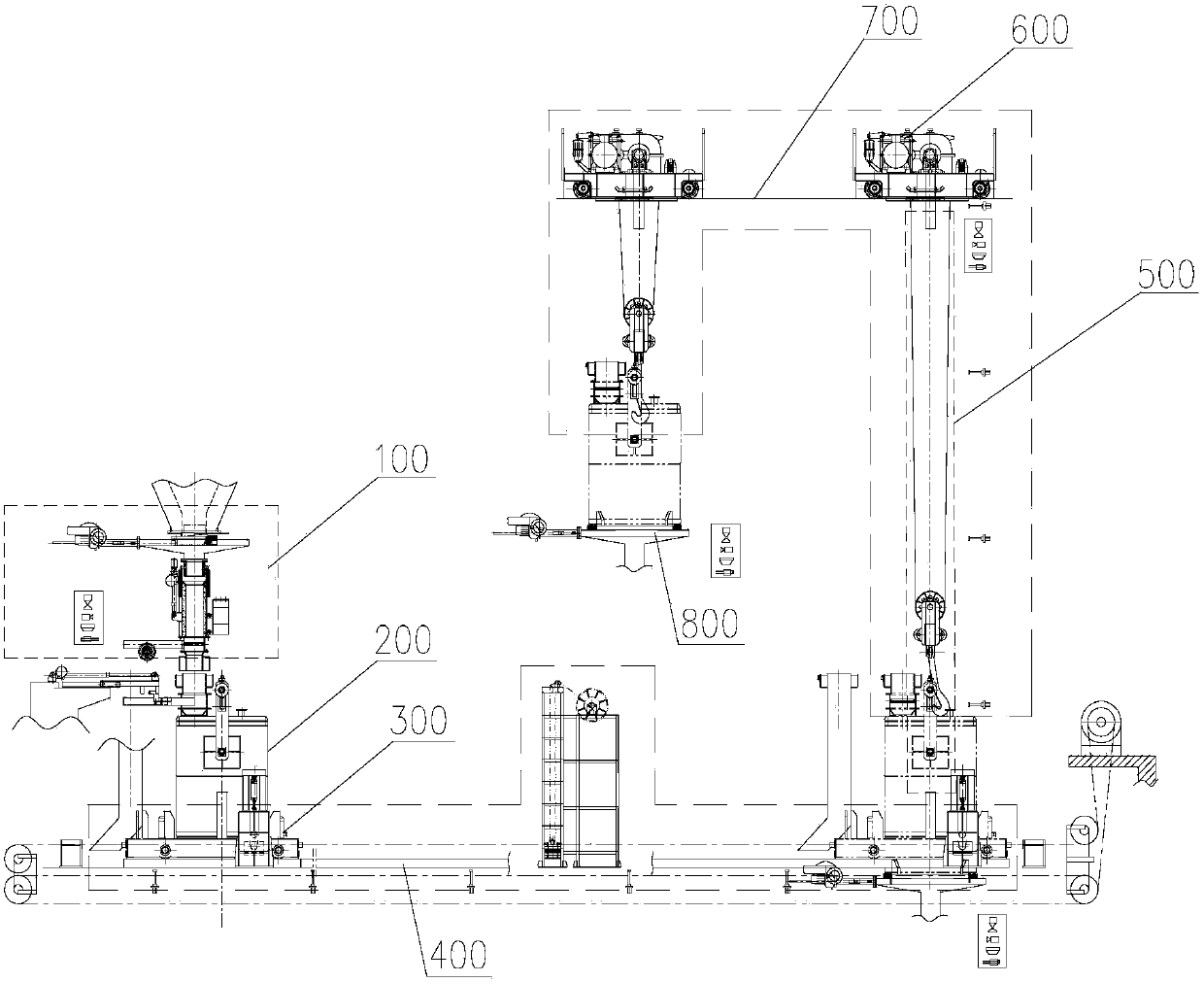
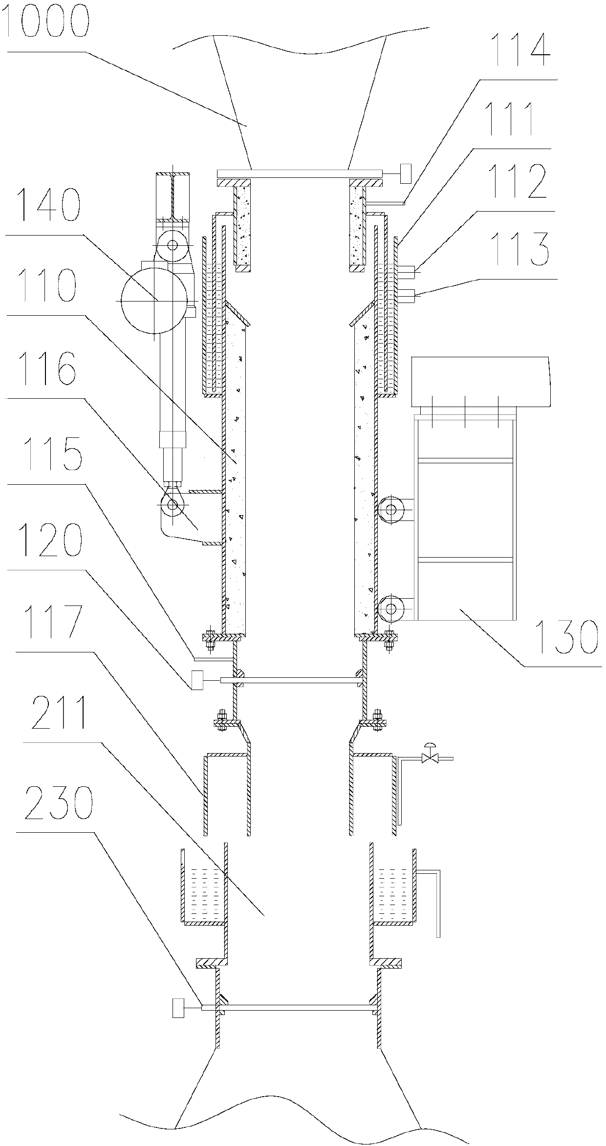
[0173] Embodiment 1: In the pyrolysis reaction system of the solid heat carrier coal graded refining of a set of coal handling capacity 3000 tons / day, adopted the above-mentioned material airtight conveying system of the present invention for its solid heat carrier (hot semi-coke) ) delivery. The high-temperature solid material in this example is hot semi-coke, the temperature of the material is 600°C, the particle size of the material is 6-25mm, the outer diameter of the tank is 1.7m, the height is 2.2m, the effective volume is 1.3m3, and the loading capacity is 600kg each time. , Combined with the weight of the equipment, the total weight is about 7 tons, that is, the weight of each transportation and lifting is about 7 tons. The loading tank with hot materials can be moved horizontally and lifted / lowered by hoisting and transferring tooling, realizing the cycle of hot semi-coke.

[0174] When carrying out the airtight transportation of high-temperature solid materials thro...


PUM


Abstract

The present invention discloses a pyrolysis reaction system, which comprises a pyrolysis reactor (1000), a material feeding device, a material return device and a pyrolysis pre-mixer (3), wherein thematerial feeding device is connected to the pyrolysis pre-mixer so as to introduce a pyrolysis material, the material return device is used for reheating at least part of the pyrolyzed solid materialdischarged from the pyrolysis reactor so as to be used as a solid heat carrier and returning the solid heat carrier to the pyrolysis pre-mixer, the pyrolysis material and the solid heat carrier are pre-mixed in the pyrolysis pre-mixer, the pre-mixed materials enter the pyrolysis reactor, a pyrolysis reaction is performed, the pyrolysis material is the mixture of coal and a viscous material, the material feeding device comprises a material pre-mixer (8), the mixture is pre-mixed by the material pre-mixer (8) and then enters the pyrolysis pre-mixer, and the coal is dried by a dryer (11). According to the present invention, with the material return loading mode of the solid heat carrier, the heat energy efficiency is high, the effect is good, the utilization of the pyrolysis material is complete, and the heat energy loss is reduced; and the co-pyrolysis problem of the coal and the viscous material is solved.

Description

technical field [0001] The invention belongs to the technical field of coal chemical industry, and in particular relates to a pyrolysis reaction system of coal and its liquefaction residue. Background technique [0002] Low-rank coal has high moisture content, low calorific value, low mechanical strength, and poor chemical stability. These characteristics make it difficult to achieve high efficiency in storage, transportation and utilization. At the same time, in the process of direct coal liquefaction, a direct liquefaction residue with a coal input of 30wt% is produced. The liquefaction residue contains a large amount of heavy oil and asphaltenes, and the sulfur content is as high as about 3%. The direct use value is low and the processing and utilization are difficult. Coal liquefaction residue is a high-carbon, high-sulfur, and highly volatile substance, and contains a large amount of direct coal liquefaction catalysts. Its effective use can not only solve environmental ...

Claims


Application Information

Patent Timeline
IPC IPC(8): C10G1/08
Inventor 郭屹郭治秦强杜铭华李君吴昌宁麻林巴黎明顾佥张朝环刘书贤陈微张颖
Owner CHNA ENERGY INVESTMENT CORP LTD
Learn More