Thermal coupling power generation system of garbage incinerator medium pressure steam and coal-fired unit

A technology for waste incinerators and coal-fired units, which is applied to steam engine devices, machines/engines, mechanical equipment, etc. It can solve problems such as low dioxin smoke emission indicators, low unit efficiency, low-temperature corrosion at the tail, and achieve system savings Equipment and operating costs, reducing coal consumption for power generation, and increasing the temperature of feed water

Active Publication Date: 2018-01-09
HARBIN BOILER
View PDF2 Cites 7 Cited by
  • Summary
  • Abstract
  • Description
  • Claims
  • Application Information

AI Technical Summary

Problems solved by technology

[0002] Garbage furnace incineration, for the purpose of disposing of garbage, uses the heat of incineration to arrange a waste heat boiler with a superheater in the furnace. The working medium circulation efficiency of this waste heat furnace is very low, about 20%, which is far lower than that of large coal-fired units of about 46%. efficiency
At the same time, there are many problems to be solved in the garbage furnace, such as high equipment investment, high-temperature corrosion of the heating surface, low-temperature corrosion of the tail, fly ash slagging, low dioxin flue gas emission indicators, serious pollution that cannot be removed, etc.

Method used


Image

  • Thermal coupling power generation system of garbage incinerator medium pressure steam and coal-fired unit

Examples


Embodiment 1

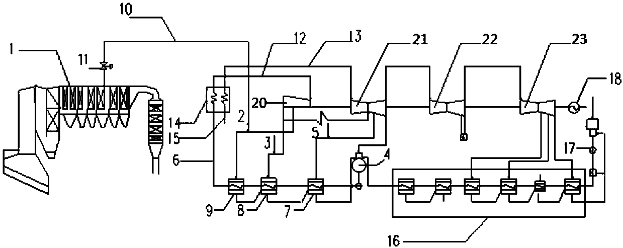
[0022] refer to figure 1 , the thermodynamically coupled power generation system of medium-pressure steam of the waste incinerator and the coal-fired unit, including the waste furnace body 1, the feed water pump 17, the low-pressure heater 16, the deaerator 4, the high-pressure heater, the water supply pipeline 6, and the coal-fired unit 14. Main steam pipeline 12, reheater pipeline 13, ultra-high pressure cylinder 20, high pressure cylinder 21, condenser 18, primary steam extraction pipeline 2 and secondary steam extraction pipeline 3, and the high pressure heater includes interconnected The first-level high-pressure heater 7 and the second-level high-pressure heater 8, the ultra-high pressure cylinder 20 is connected to the high-pressure cylinder 21, the feed water pump 17 is connected to the low-pressure heater 16 through the pipeline, and the low-pressure heater 16 is connected to the deaerator 4 through the pipeline, The deaerator 4 is connected to the high-pressure heate...

Embodiment 2

[0027] The steam outlet of the garbage furnace body 1 is connected to the secondary steam extraction pipeline 3 through a pipeline 10 .

Embodiment 3

[0029] The steam outlet of the garbage furnace body 1 is connected with the deaerator 4 through the pipeline 10 .

[0030] work process:

[0031] The feed water enters the low-pressure heater 16 through the feed water pump 17, and then enters the third-stage high-pressure heater 7, the second-stage high-pressure heater 8, and the first-stage high-pressure heater 9 through the deaerator 4, and then is sent into the large coal-fired boiler through the water supply pipeline 6. Unit 14, the high-temperature and high-pressure main steam generated by the combustion of the coal-fired unit 14 enters the ultra-high pressure cylinder 20 through the main steam pipeline 12 to perform work, wherein the steam extracted from the ultra-high pressure cylinder 20 is used to heat the secondary high-pressure heater 8 and the tertiary The high-pressure heater 7 and most of the exhaust gas from the ultra-high-pressure cylinder 20 enter the reheater system 15 of the coal-fired unit 14, and the rehea...


PUM


Abstract

The invention discloses a thermal coupling power generation system of a garbage incinerator medium pressure steam and coal-fired unit. The thermal coupling power generation system is technically characterized in that a garbage incinerator body and a coal-fired unit are included; a high-pressure heater comprises a first-stage high-pressure heater body and a second-stage high-pressure heater body which communicate with each other; an ultrahigh-pressure cylinder is connected with a high-pressure cylinder; a water feed pump is connected with a low-pressure heater through a pipeline and is connected with a deaerator through a pipeline; the deaerator is connected with the high-pressure heater through a pipeline; the high-pressure heater is connected with the coal-fired unit through a water feedpipeline; the coal-fired unit is connected with a main steam pipeline; the main steam pipeline is connected with the ultrahigh-pressure cylinder; the ultrahigh-pressure cylinder is connected with a third-stage high-pressure heater body through a first-stage steam extraction pipeline; the ultrahigh-pressure cylinder is connected with the second-stage high-pressure heater body through a second-stagesteam extraction pipeline; the coal-fired unit is connected with the high-pressure cylinder through a reheater pipeline; and the high-pressure cylinder is connected with a condenser. According to thethermal coupling power generation system, by means of steam generated by a waste heat boiler for incinerating garbage, the steam is guided into a coal-fired unit thermal system, the efficiency of garbage incineration power generation is improved, and thermal consumption and power generation consumption are reduced.

Description

Technical field: [0001] The invention relates to the technical field of boiler power generation, in particular to a thermodynamic coupling power generation system of medium-pressure steam in a waste incinerator and a coal-fired unit. Background technique: [0002] Garbage furnace incineration, for the purpose of disposing of garbage, uses the heat of incineration to arrange a waste heat boiler with a superheater in the furnace. The working medium circulation efficiency of this waste heat furnace is very low, about 20%, which is far lower than that of large coal-fired units of about 46%. efficiency. At the same time, there are many problems to be solved in the garbage furnace, such as high equipment investment, high-temperature corrosion of the heating surface, low-temperature corrosion of the tail, fly ash slagging, low dioxin flue gas emission indicators, and serious pollution that cannot be removed. Invention content: [0003] In order to overcome the above problems, th...

Claims


Application Information

Patent Timeline
Patent Type & Authority Applications(China)
IPC IPC(8): F01K13/00F01K11/02F01D15/10F22D1/50
Inventor 于强施登宇黄莺苗闪闪韩升利于景泽殷亚宁
Owner HARBIN BOILER
Why Eureka
Try Eureka