
Flake ice potential tower turbulent flow heat pump

A potential tower and ice chip technology, which is applied in the field of ice chip potential tower turbulent flow heat pump, can solve the problems of hydrostatic level pressure loss, poor antifreeze performance, and large loss

Pending Publication Date: 2018-01-09
刘秋克
View PDF0 Cites 2 Cited by
  • Summary
  • Abstract
  • Description
  • Claims
  • Application Information

AI Technical Summary

Problems solved by technology

[0006] The purpose of the turbulent flow heat pump of the ice chip potential tower of the present invention is to economically and rationally apply the chlorine-free environmental protection multi-chain anti-floating ice chip solution in the open heat source tower to carry out the ice-water phase transition process to absorb the low-temperature potential energy in the air, effectively Solved the problems of environmental pollution and excessive loss of chlorine salt open heat source towers in the Yangtze River Basin
The evaporator shell-side cold water phase-change ice chip heat transfer and the tube-side working medium turbulent heat transfer solve the problem that the flooded evaporator is used as an open heat source tower to obtain heat due to unstable solution concentration resulting in poor antifreeze performance
In the north, the turbulent heat transfer of the working fluid in the tube engineering of the closed heat source tower for heat extraction and evaporator is used, which solves the problem of static liquid level pressure loss and low temperature oil return of the flooded evaporator; solves the problem of the working medium flow rate of the falling film evaporator with the low temperature of the compressor. And cause the problem of low performance of falling film area reduction

Method used


Image

  • Flake ice potential tower turbulent flow heat pump

Examples


Embodiment Construction

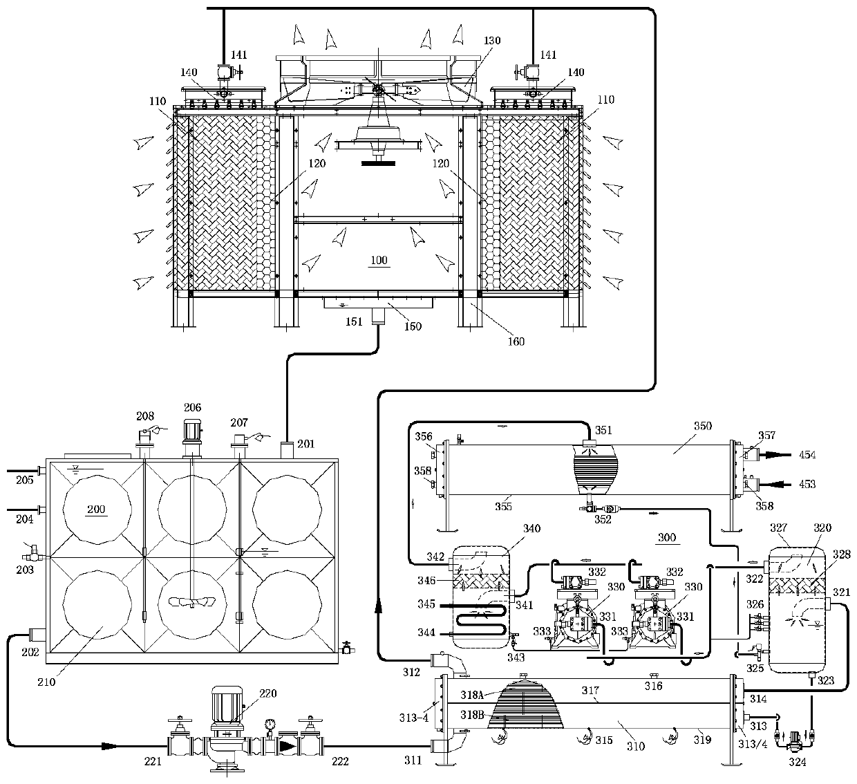
[0017] The following is combined with the accompanying drawings: figure 1 The schematic diagram of the connection structure of the "ice debris potential tower turbulent flow heat pump" of the present invention is further described.

[0018] With reference to accompanying drawing, the turbulent flow heat pump of the ice chips potential tower of the present embodiment.

[0019] Explanation: The hollow arrows in the figure indicate the air flow direction, and the solid arrows indicate the circulation flow direction of the circulating medium, working liquid and water body.

[0020] The ice chip potential tower turbulent flow heat pump comprises an ice chip phase change heat source tower (100), a cooling liquid regulating circulation station (200), and an ice chip phase change turbulent flow heat pump unit (300).

[0021] The ice chip phase change heat source tower (100) includes a symmetrical wetting filler (110), a symmetrical mist collector (120), a pneumatic device (130), a sy...


PUM


Abstract

The purpose of the turbulent flow heat pump of the ice debris potential tower of the present invention is that the negative temperature and air temperature in the Yangtze River Basin are less in winter, and the open potential tower absorbs the low-temperature potential energy in the air through the chloride-free multi-chain anti-drifting ice debris solution to melt into a cold water solution and enter into evaporation. The shell side releases low-temperature potential energy to the turbulent working medium in the tube side to become an ice chip solution, which solves the environmental pollution of hot salt spray in the chlorine salt open tower, and the diluted cold water solution fills the tube side of the evaporator, which may easily cause frost heaving and cracking of the finned tube. problem, improve the antifreeze performance of the whole machine, and use turbulent working fluid heat transfer in the northern evaporator tube side, which solves the problem of static liquid level pressure loss and low temperature oil return difficulties in large flooded evaporators; solves the problem of falling film evaporator working fluid The problem of the reduction of the falling film area caused by the flow decay with the low temperature of the compressor.

Description

technical field [0001] The "ice debris potential tower turbulent flow heat pump" involved in the present invention relates to the two major fields of my country's new energy and energy-saving technology, environmental protection and resources. Background technique [0002] Under the current energy-saving and low-carbon, green and low-carbon buildings that reduce smog and haze, the closed heat source tower plays a role in low-carbon buildings as a low-carbon, environmentally friendly, and energy-saving heating method that is used as a heat pump cold (heat) source without frost. However, the research on bidding projects and operation monitoring shows that the early low-cost chlorine-salt open-type heat source tower heat pumps are mostly used, and the problems are environmental pollution and economical issues. [0003] The chlorine salt open heat source tower heat pump system is used in the Yangtze River Basin of my country. In winter, the cheap chlorine salt freezing solution ...

Claims


Application Information

Patent Timeline
IPC IPC(8): F25B30/06F25B30/04
Inventor 刘秋克栾桂吉陈欣雅宋立禄
Owner 刘秋克
Learn More