
Artificial chordae tendineae and artificial chordae tendineae implanting system

An artificial chordae tendineae and chordae tendineae technology, applied in the field of medical devices, can solve the problems of surgical failure, artificial chordae tendineae shedding, increased valve leaflet tearing, etc., achieve stable and reliable indirect connection, speed up the postoperative healing process, and shorten the operation. effect of time

Active Publication Date: 2018-01-12
HANGZHOU VALGEN MEDTECH CO LTD
View PDF7 Cites 26 Cited by
  • Summary
  • Abstract
  • Description
  • Claims
  • Application Information

AI Technical Summary

Problems solved by technology

[0005] a) The puncture point formed by the needle with a hook-shaped tip on the valve leaflet is too large, causing greater damage to the valve leaflet, which not only affects the recovery process of the patient after surgery, but also increases the risk of the valve leaflet being torn after surgery;
[0006] b) The contact between the implanted artificial chordae and the leaflet is only a single force point, and the long-term pulling of the artificial chordae on the leaflet may easily cause the leaflet to tear;
[0007] c) The probability of the needle hooking the artificial chord is relatively low, resulting in a low success rate of the operation and prolonging the operation time;
[0008] d) After the needle hooks the artificial chord, since the needle and the artificial chord are only connected by weak friction force, during the process of withdrawing the needle, the artificial tendon will be damaged due to the patient's blood flow or the operator's action. The cable is easy to fall off from the needle, causing the operation to fail and prolonging the operation time

Method used


Image

  • Artificial chordae tendineae and artificial chordae tendineae implanting system
  • Artificial chordae tendineae and artificial chordae tendineae implanting system
  • Artificial chordae tendineae and artificial chordae tendineae implanting system

Examples


Embodiment 1

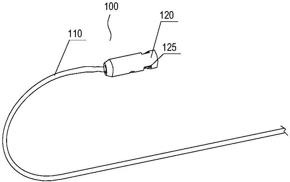
[0071] Such as Figure 3-9 As shown, the artificial chord 100 of the first embodiment includes a flexible chord main body 110 . The chord main body 110 is used to be implanted in the heart to replace the diseased chord in the heart. The chord body 110 has opposing first and second ends. The first end and / or the second end are connected with a fixing member 120 . The side of the fixing member 120 facing away from the chord main body 110 is provided with a puncture connecting member 125 for non-detachable fixed connection or detachable fixed connection with the puncture needle.

[0072] One end of the chordae main body 110 is fixed on the leaflet, and the other end can be fixed on the ventricular wall or the mastoid muscle to replace the diseased chordae and maintain the tension between the leaflet and the ventricular wall. The flexibility of the chord main body 110 means that it can be bent arbitrarily without stretching in the axial direction. Generally, the chord main body...

Embodiment 2

[0088] Such as Figure 11-Figure 23 As shown, the artificial chord tendon implantation system provided in Embodiment 2 is used to implant the artificial chord tendon 100 into the patient's heart to replace the diseased chord tendon. The artificial chord implantation system of this embodiment includes an artificial chord 100 , a clamping device 300 , a puncturing device 400 and a pushing device 200 . The pushing device 200 includes a pushing catheter 210 . The pushing catheter 210 is provided with a plurality of through lumens along the axial direction. The piercing device 400 and the clamping device 300 are respectively movably mounted in different lumens of the pushing catheter 210 . The clamping device 300 includes a clamping push rod 330 , a distal clamp 310 and a proximal clamp 320 for cooperating to clamp the leaflet. The proximal collet 320 is disposed at the distal end of the pushing catheter 210 , and the distal collet 310 is disposed at the distal end of the clampi...

Embodiment approach

[0093] Such as Figure 14-15 As shown, the first embodiment is: the chord connecting member 411 is arranged at the distal end of the puncture needle 410 and forms an interference fit, a snap connection or a key connection with the fixing member 120, or at least one protruding tooth or at least one Circle convex edge.

[0094] For the interference fit connection, since the side of the fixing member 120 facing away from the chord main body 110 is provided with an accommodating cavity 121, at this time the whole or part of the outer diameter of the puncture needle 410 can be made larger than the width or inner diameter of the accommodating cavity 121, The two are closely fitted and plugged together to form a fixed connection with an interference fit. The chordal connector 411 is preferably provided with a protruding tooth or rim behind the straight tip of the puncture needle 410 . It can be understood that, in other embodiments, at least one groove or hole can also be provided ...


PUM


Abstract

The invention discloses artificial chordae tendineae and an artificial chordae tendineae implanting system. The artificial chordae tendineae comprises a flexible chordae tendineae main body, wherein the first end and / or the second end of the chordae tendineae main body are / is connected with a fixing element; and a puncture connecting element is arranged at one side, backing to the chordae tendineae main body, of the fixing element. The artificial chordae tendineae implanting system comprises a clamping device, a puncture device and a pushing device, wherein the pushing device comprises a pushing guide pipe; the puncture device and the clamping device are arranged in different inner cavities of the pushing guide pipe in a penetrating way; the clamping device comprises a clamping push rod, afar end clamp head and a near end clamp head; the near end clamp head is arranged at the far end of the pushing guide pipe; the far end clamp head is arranged at the far end of the clamping push rod;the artificial chordae tendineae is accommodated in the clamping device; the fixing element of the artificial chordae tendineae corresponds to a puncture needle head; the puncture device comprises the puncture needle head and a puncture push rod; the puncture push rod is connected with the near end of the puncture needle head; and the far end of the puncture needle head is a cone-shaped straightsharp end. The artificial chordae tendineae and the puncture needle head form stable connection; the puncture point is small; the injury on valve leaflets is reduced; and the operation time is reduced.

Description

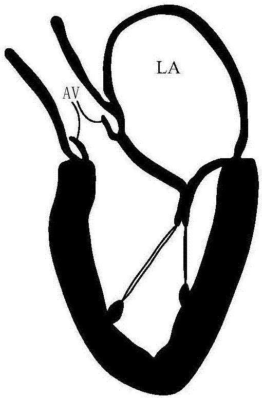
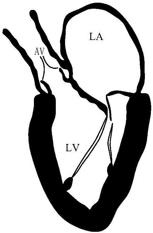
technical field [0001] The invention belongs to the technical field of medical devices, and relates to a device for repairing heart valve defects, in particular to an artificial chord and its artificial chord implantation system. Background technique [0002] The mitral valve is a one-way "valve" between the left atrium (abbreviation: LA) and the left ventricle (abbreviation: LV), which can ensure blood flow from the left atrium to the left ventricle. See figure 1 , A normal healthy mitral valve has multiple chordae (referred to as: CT). The leaflets of the mitral valve are divided into anterior leaflet and posterior leaflet. When the left ventricle is in a diastolic state, the two are in an open state, and blood flows from the left atrium to the left ventricle; when the left ventricle is in a systolic state, the chordae are stretched to ensure The valve leaflets will not be rushed to the atrium side by the blood flow, and the front and rear leaflets are well closed, there...

Claims


Application Information

Patent Timeline
Patent Type & Authority Applications(China)
IPC IPC(8): A61F2/24
CPCA61B17/0401A61F2/2457A61F2/2466A61B2017/00243A61B17/0469A61B2017/0406A61B2017/0409A61B2017/0472A61B2017/06042A61B2017/0495A61B17/3468A61F2220/0016
Inventor 张庭超张伟伟周春远
Owner HANGZHOU VALGEN MEDTECH CO LTD
Learn More