Laser additive manufacturing device and method

A laser additive and equipment technology, applied in the field of additive manufacturing, can solve the problems that the actual laying thickness of the metal powder layer deviates from the preset value, affects the forming accuracy and service performance of metal components, and has high design, assembly and maintenance costs. The complexity of the process and the difficulty of operation are reduced, the forming accuracy and service performance are guaranteed, and the effect of reducing the difficulty of cleaning and recycling

Pending Publication Date: 2018-01-12
HUAZHONG UNIV OF SCI & TECH
View PDF9 Cites 13 Cited by
  • Summary
  • Abstract
  • Description
  • Claims
  • Application Information

AI Technical Summary

Problems solved by technology

However, this technology requires the integration of powder nozzles, CNC machine tools, laser heads and scanning galvanometers, and the deposition of closed thin-walled and sliced ​​layers of metal components requires the use of laser beams with completely different optical parameters and the application of completely different scanning parameters. , resulting in high equipment design, assembly and maintenance costs, high process complexity and difficult o

Method used


Image

  • Laser additive manufacturing device and method
  • Laser additive manufacturing device and method

Examples


Example Embodiment

[0030] Example 1

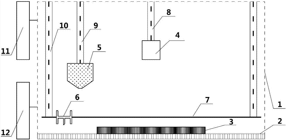
[0031] Such as figure 1 As shown, a laser additive manufacturing equipment provided by an example of the present invention includes a forming cabin 1, a working platform 2, a substrate 3, a scanning galvanometer assembly, a powder preset assembly, an atmosphere control assembly 11, a lifting assembly, and a central control system 12.

[0032] The working platform 2 is located at the lower part of the forming cabin 1, and the base plate 3 is fixedly installed on the surface of the working platform 2;

[0033] The scanning galvanometer assembly includes a scanning galvanometer 4, the scanning galvanometer 4 is connected to a laser source through a connecting optical path, and the powder preset assembly includes a powder storage hopper 5, a powder spreader 6 and a first moving mechanism 7; The powder container 6 is used to receive the metal powder provided by the powder storage hopper 5, and is driven by the first moving mechanism 7 to preset a metal powder layer abo...

Example Embodiment

[0044] Example 2

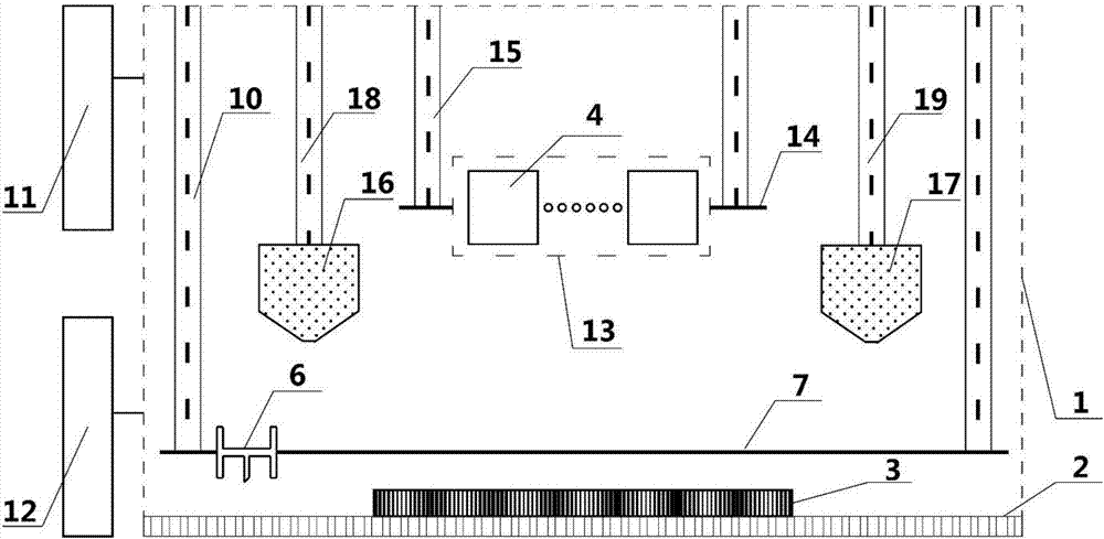
[0045] Such as figure 2 As shown, a laser additive manufacturing equipment provided by an example of the present invention includes a forming cabin 1, a working platform 2, a substrate 3, a scanning galvanometer assembly, a powder preset assembly, an atmosphere control assembly 11, a lifting assembly, and a central control system 12.

[0046] The working platform 2 is located at the lower part of the forming cabin 1, and the base plate 3 is fixedly installed on the surface of the working platform 2;

[0047] The scanning galvanometer assembly includes several scanning galvanometer mirrors 4 (the number of units ≥ 2), which constitute a scanning galvanometer array 13; each scanning galvanometer 4 is connected to the optical path by connecting the optical path to the laser source; the scanning galvanometer assembly also includes The fifth moving mechanism 14 is used to drive the scanning galvanometer array 13 to move in the horizontal direction, so as to realize t...


PUM


Abstract

The invention discloses a laser additive manufacturing device and method. The laser additive manufacturing device comprises a forming cabin, a working platform, a substrate, a scanning galvanometer assembly, a powder presetting assembly, an atmosphere regulating assembly, a lifting assembly and a central control system; when the laser additive manufacturing device is applied to the forming of a metal component, the scanning galvanometer assembly is not only used for the layer-by-layer selective melting of slice layers of the metal components above the fixedly-positioned substrate, but also used for the layer-by-layer selective melting of enclosed thin walls above the substrate; and the enclose thin walls are matched with the slice outline of the metal component, and capable of accommodating a metal powder bed. The laser additive manufacturing device and method disclosed by the invention have the advantages that the forming space is flexible and adjustable as well as the powder utilization ratio is high; and the high-quality low-cost additive manufacturing of metal components of various sizes and shapes can be achieved.

Description

technical field [0001] The invention belongs to the technical field of additive manufacturing, and in particular relates to a low-cost laser additive manufacturing equipment and method capable of forming complex metal components with flexible and adjustable forming space and excellent forming quality. Background technique [0002] Laser additive manufacturing technology is expected to realize the integrated processing of the structure and function of metal components, which is a research hotspot in the advanced manufacturing industry. According to the different process characteristics, the commonly used laser additive manufacturing technology can be divided into two types: laser cladding deposition and laser selective melting. [0003] The process principle of laser cladding deposition technology can be summarized as follows: 1) The laser head outputs the laser beam according to the preset trajectory under the control of the CNC machine tool, and scans the fixed substrate; 2...

Claims


Application Information

Patent Timeline
IPC IPC(8): B22F3/105B33Y10/00B33Y30/00
CPCY02P10/25
Inventor 曾晓雁魏恺文李祥友朱海红王泽敏
Owner HUAZHONG UNIV OF SCI & TECH
Why Eureka
Try Eureka