A method of atomic deposition

A technology of atomic deposition and plasma, which is applied in metal material coating technology, coating, gaseous chemical plating, etc., can solve the problems of film quality degradation, reduction of film growth process control accuracy, ion beam current loss, etc., and achieve structural compact effect

Active Publication Date: 2019-06-04
青岛四方思锐智能技术有限公司
View PDF6 Cites 0 Cited by
  • Summary
  • Abstract
  • Description
  • Claims
  • Application Information

AI Technical Summary

Problems solved by technology

Ion source is the core component of ion beam assisted deposition, but existing wide-beam ion source has the defective of following technology: (1) the ion beam emitted by some active gas such as hydrogen as source gas wide-beam ion source usually contains polyatomic a mixture of hydrogen ions and monatomic hydrogen ions, H 2 + , H + , their ratio can only be adjusted within a narrow range without changing other beam parameters; (2) Each ion species of molecules and atoms has an independent energy distribution, which cannot be adjusted individually. In the ion beam colliding with the surface of the film, various components overlap each other, resulting in the broadening of the energy distribution, which reduces the control accuracy of the film growth process and leads to a decline in the quality of the film; (3) based on magnetic field or based on Electrostatic ion mass filtering method, will cause the loss of ion beam current, especially in the case of lower ion energy, the described one atom deposition method can solve the above problems

Method used


Image

  • A method of atomic deposition
  • A method of atomic deposition
  • A method of atomic deposition

Examples


Embodiment Construction

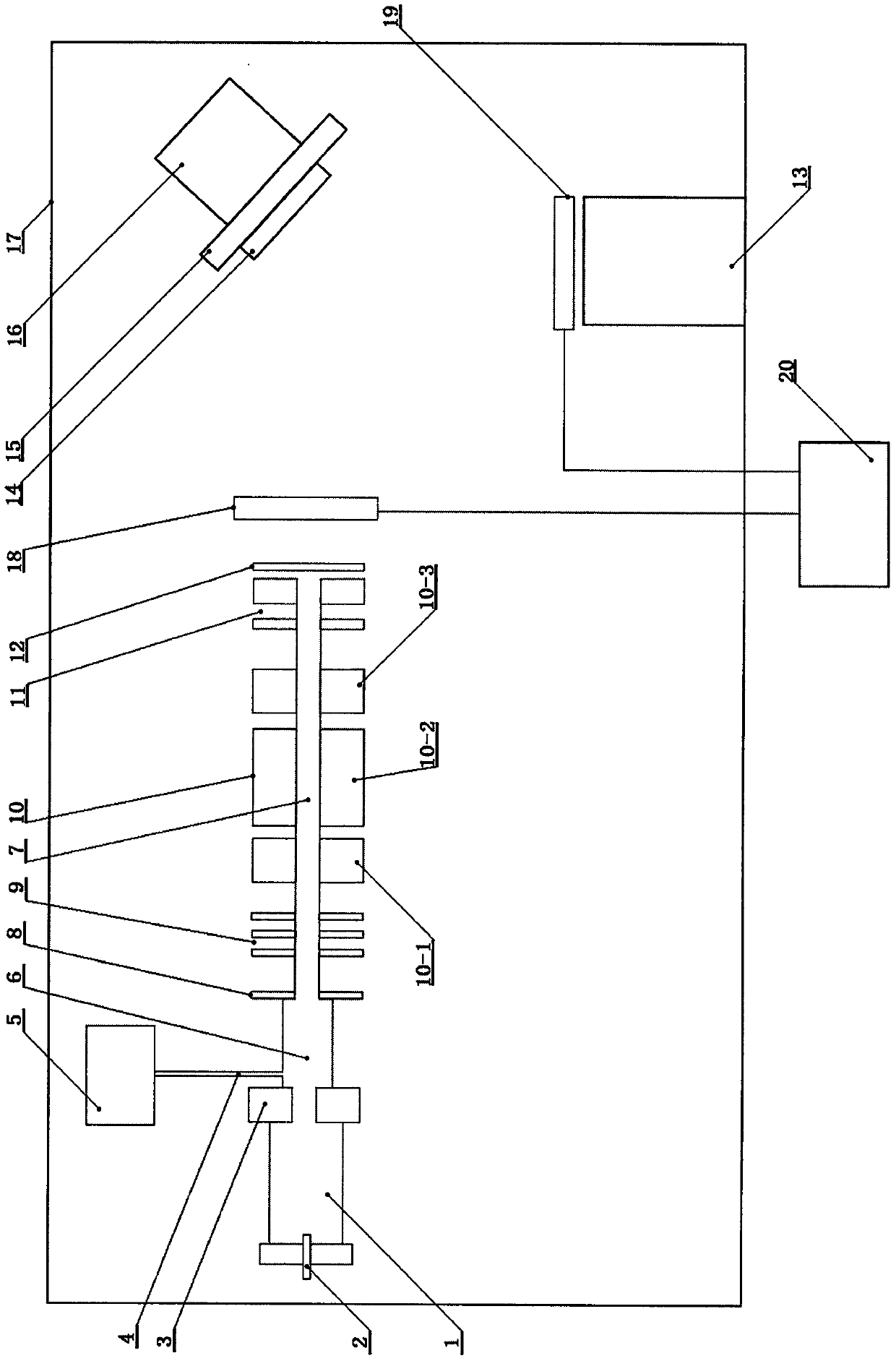
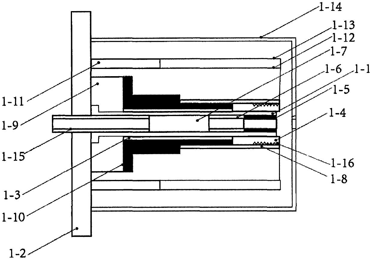
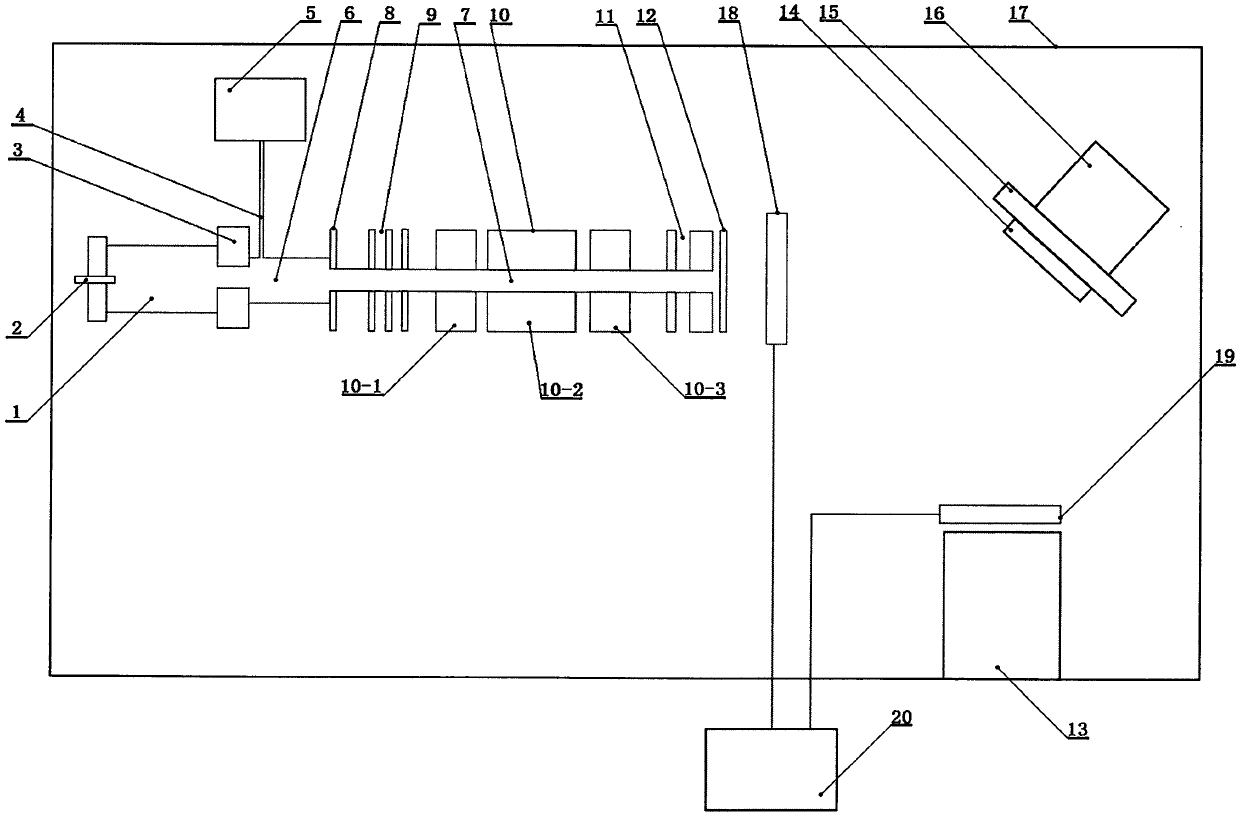
[0030] Such as figure 1 It is a schematic diagram of the structure of the present invention, such as figure 2 It is a schematic diagram of the enlarged structure of the hollow cathode. The device mainly includes an ion beam composed of a hollow cathode (1), a trigger module (2), an anode (3), a gas pipe (4), a gas storage tank (5), and a plasma chamber (6). Source, drift tube (7), extraction electrode (8), electrode group I (9), three independent quadrupole group I (10-1), quadrupole group II (10-2), quadrupole Quadrupole rod (10) composed of rod group III (10-3), electrode group II (11), stainless steel grid (12), electron beam evaporation source (13), sample (14), sample stage (15), Displacement stage (16), vacuum chamber (17), baffle plate I (18), baffle plate II (19), control unit (20) and cable, described hollow cathode (1) mainly comprises graphite cathode tube (1-1 ), stainless steel base (1-2), aluminum inner sleeve (1-3), ceramic heating tube (1-4), launch tube (1-...


PUM


Abstract

The invention relates to the technical field of film material preparation, and discloses an atom deposition method. The atom deposition method comprises the steps that neutral gas such as argon gas orhelium gas is introduced into a plasma chamber; hydrogen gas is introduced into a hollow cathode; a heating wire made of rhenium is galvanized, voltage is applied between an anode and the hollow cathode, the anode is kept to be grounded, negative voltage is applied to the hollow cathode and gradually increased to minus 55 kV from minus 2 kV, breakdown is generated between the anode and the hollowcathode, and H2<+> ions and H<+> ions are generated; sinusoidal voltage U<RF1>, sinusoidal voltage U<RF2> and sinusoidal voltage U<RF3> which have the frequency of 2 MHz, the different amplitudes andthe voltage peak values not exceeding 1.5 Kv are applied to quadrupole rods; direct-current potential U<DC1> is applied to a first quadrupole rod group, and direct-current potential U<DC3> is appliedto a third quadrupole rod group; the ions generated in the step 3 pass through the quadrupole rods and then enter a second quadrupole rod group, the ions are converged or deflected, and ion beams pass through a stainless steel grid mesh; a molecular sample to be deposited is evaporated through an electron beam evaporation source; and parameters of a displacement platform are adjusted to enable asample platform to be driven to rotate at a constant speed, and therefore a film grows more uniformly.

Description

technical field [0001] The invention relates to the technical field of thin film material preparation, in particular, it utilizes a compact ion beam assisted deposition device for ion quality and ion energy selection to generate a hydrogen ion flow with variable ion energy. When the ion beam current is sufficiently high An atom deposition method that can independently select ion mass and quadrupole mass filtration only depends on electric field and has no magnetic field. Background technique [0002] Ion beam assistance is a method of thin film deposition, which refers to the use of ion beams generated by ion sources in a high-vacuum evaporation chamber to bombard the substrate material being deposited, so as to prepare thin films with certain characteristics. The main process of the ion beam assisted deposition process is to bombard the growing film with appropriate charged ions during the coating process, thus changing the film-forming environment. At this time, due to th...

Claims


Application Information

Patent Timeline
Patent Type & Authority Patents(China)
IPC IPC(8): C23C16/455
Inventor 李君华方晓华张向平
Owner 青岛四方思锐智能技术有限公司
Why Eureka
Try Eureka