
Radio frequency elastic contact structure used for welding-free interconnection

An elastic contact and radio frequency technology, applied in the direction of connection, two-pole connection, two-part connection device, etc., can solve the problems that the adapter can no longer be installed, the structure cannot be disassembled, and the plugging force is large, so as to facilitate subsequent maintenance and replacement and meet Actual use requirements, the effect of increasing the creepage distance

Inactive Publication Date: 2018-01-19
SHANGHAI AEROSPACE SCI & IND ELECTRIC APPLIANCE RES INST
View PDF3 Cites 3 Cited by
  • Summary
  • Abstract
  • Description
  • Claims
  • Application Information

AI Technical Summary

Problems solved by technology

This structure obviously increases the cost of use. More importantly, the existing installation space is already very narrow, and it is impossible to install the adapter; in addition, when multiple connectors are used together, not only may cause dimensional interference, but also The pulling force is very large, which cannot meet the actual needs of use
[0005] In addition, connecting pins can also be provided on the connector, and the connecting pins can be inserted into the plated through holes, or fixed together by soldering. Obviously, this connection method not only complicates the assembly process, but also cannot guarantee the stability of the assembly quality. The structure cannot be disassembled and cannot meet actual needs

Method used


Image

  • Radio frequency elastic contact structure used for welding-free interconnection
  • Radio frequency elastic contact structure used for welding-free interconnection
  • Radio frequency elastic contact structure used for welding-free interconnection

Examples


Embodiment Construction

[0018] The content of the present invention will be described below in conjunction with specific embodiments.

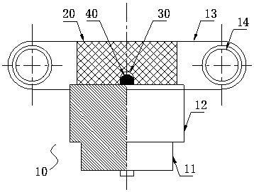
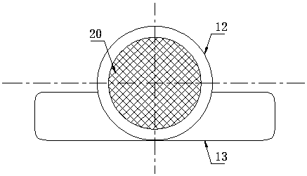
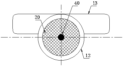
[0019] Such as figure 1 Shown is the front view of the RF elastic contact structure for solderless interconnection according to the present invention, figure 2 for figure 1 Top view of image 3 for figure 1 Bottom view. The radio frequency elastic contact structure of the present invention is used for mating and mating with the PCB board. The upper and lower edges of each plated through hole are also provided with counterbores, and the plated through holes are used to accommodate the radio frequency elastic contact of the present invention. For structure, the counterbore is used to fit and lock the radio frequency transmission structure of the present invention.

[0020] The radio frequency elastic contact structure of the present invention includes a casing 10 made of a copper-based alloy material. The casing 10 directly contacts the plated through holes on the PCB. A ...


PUM


Abstract

The invention discloses a radio frequency elastic contact structure used for welding-free interconnection. The radio frequency elastic contact structure is inserted and matched with a PCB; electroplating through holes are formed in the PCB; the radio frequency elastic contact structure comprises a shell made from a copper-based alloy material; the shell is in direct contact with the electroplatingthough holes in the PCB; an insulating material medium body is arranged in the central position of the shell; the medium body is directly pressed into the shell through interference fit; a blind holeis formed in the central position of the interior of the medium body; an inner conductor is arranged in the blind hole; the inner conductor is an elastic contact part; and the shell, the medium bodyand the inner conductor form a radio frequency coaxial structure. According to the structure disclosed in the invention, the shell is equivalent to an outer conductor of the existing radio frequency connector, and the shell is directly inserted and matched with the electroplating through holes in the PCB, so that the mounting space requirement is lowered to the minimum, the weight is lowered, andredundant space mounting is not occupied, multiple times of lossless and welding-free interconnecting mounting and detaching can be realized, and convenience in detachment, post maintenance and replacement is achieved.

Description

Technical field [0001] The invention relates to a radio frequency elastic contact structure, in particular to a radio frequency elastic contact structure for solderless interconnection used for printed circuit board (PCB) signal transmission, and belongs to the technical field of electrical contact interconnection. Background technique [0002] The signal transmission of the printed circuit board (PCB board) has a variety of contact forms. Usually there are several plated through holes on the PCB board, and the signal transmission is carried out by contacting with the external circuit through the external through holes. Generally, this connection structure is suitable for direct plugging and unplugging of the connector, that is, the contact pins of the connector are directly matched with the plated through holes to realize system interconnection and signal transmission. [0003] For radio frequency connectors, such as the existing SMA, BNC, TNC and other series of radio frequency c...

Claims


Application Information

Patent Timeline
Patent Type & Authority Applications(China)
IPC IPC(8): H01R24/50H01R4/48H01R103/00
Inventor 肖顺群匡秀娟
Owner SHANGHAI AEROSPACE SCI & IND ELECTRIC APPLIANCE RES INST
Learn More