Push-pull circuit and gain amplification circuit composed of same

A push-pull circuit and resistance technology, applied in the field of gain amplifying circuit and push-pull circuit, can solve the problems of limited current amplifying capacity, large loss of transistor Q2, large loss of push-pull circuit, etc., and achieve low power supply voltage and heat dissipation design. Simple, low power tube loss effect

Active Publication Date: 2018-01-30
UNITED AUTOMOTIVE ELECTRONICS SYST
View PDF5 Cites 0 Cited by
  • Summary
  • Abstract
  • Description
  • Claims
  • Application Information

AI Technical Summary

Problems solved by technology

The biggest disadvantage of this protection circuit is that the loss of transistor Q1 and transistor Q2 is relatively large. When designing and selecting, it is necessary to select a tube with a larger package and current capacity, and it is required to select a device with better heat dissipation function.
[0019] 1. The use of direct operational amplifiers has the disadvantages of limited current amplification capability and poor load capacity;
[0020] 2. The general push-pull amplifier circuit has the disadvantage of being unable to realize over-current protection.
[0021] 3. The push-pull circuit using over-current limiting protection has disadvantages such as large loss under over-current conditions, and requires a better thermal design, so the cost is high

Method used


Image

  • Push-pull circuit and gain amplification circuit composed of same
  • Push-pull circuit and gain amplification circuit composed of same
  • Push-pull circuit and gain amplification circuit composed of same

Examples


Embodiment Construction

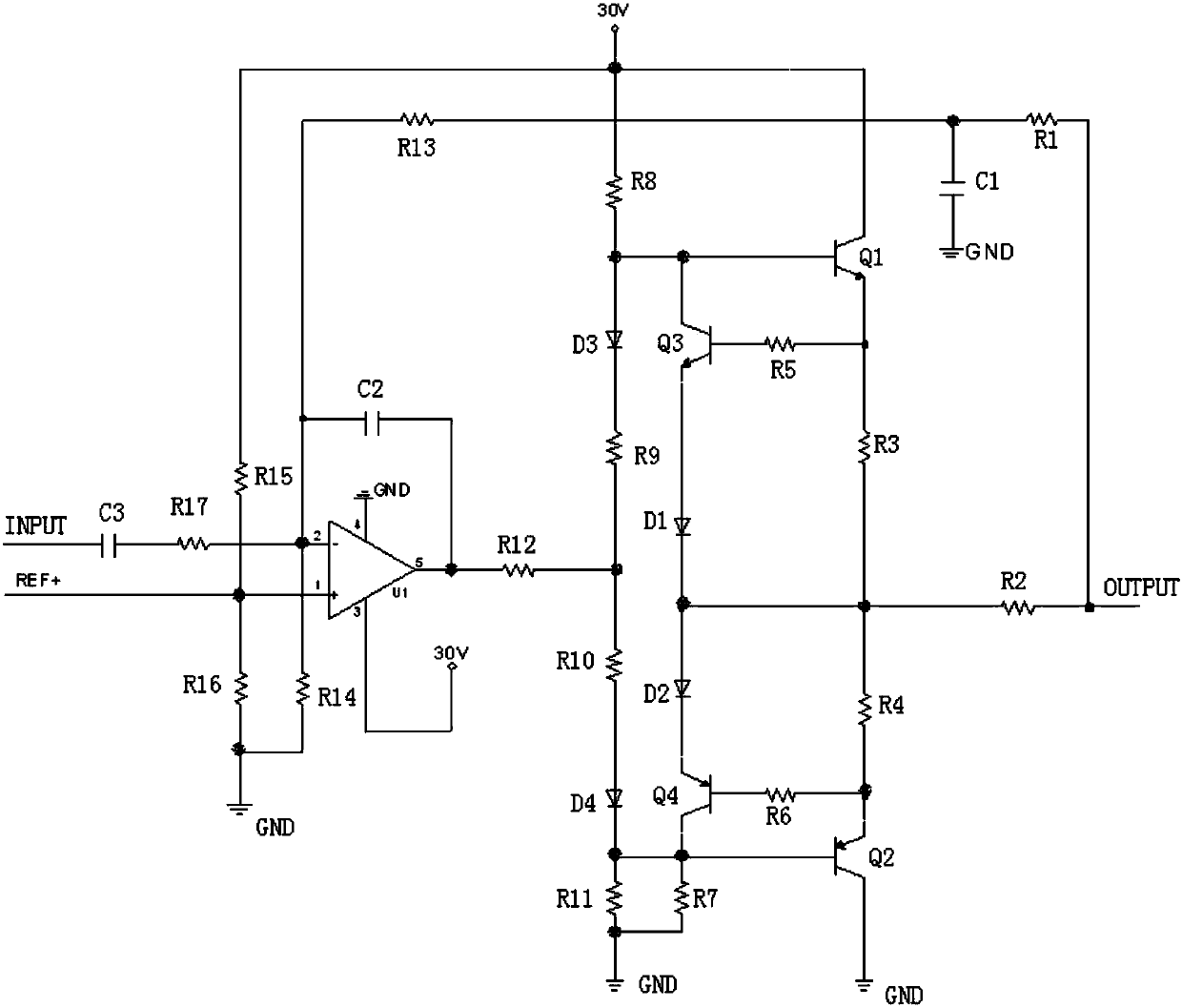
[0093] Such as Figure 4 As shown, the first embodiment of the push-pull circuit of the present invention includes:

[0094] First to fourth transistors Q1-Q4, first to sixth diodes D1-D6, first to second Zener diodes Z1, Z2 and first to sixth resistors R1-R6;

[0095] The emitter of the first triode Q1 is connected to one end of the first resistor R1, the collector of the first triode Q1 is connected to the cathode of the first diode D1, the anode of the first diode D1 is connected to the power supply terminal E, and the first triode Q1 The base is connected to the collector of the third triode Q3 and the cathode of the third diode D3;

[0096] The emitter of the second transistor Q2 is connected to one end of the second resistor R2, the collector of the second transistor Q2 is connected to the anode of the second diode D2, the cathode of the second diode D2 is grounded, and the base of the second transistor Q2 is connected to The collector of the fourth triode Q4 and the a...


PUM


Abstract

The invention discloses a push-pull circuit. According to the push-pull circuit, an emitting electrode of a triode I is connected with one end of a resistor I, a collector electrode of the triode is connected with a negative electrode of a diode I, a base electrode of the triode is connected with a collector electrode of a triode III and a negative electrode of a diode III, and a positive electrode of the diode I is connected with the power end. An emitting electrode of a triode II is connected with one end of a resistor II, a collector electrode of the triode II is connected with a positive electrode of a diode II, and a base electrode of the triode II is connected with a collector electrode of a triode IV and a positive electrode of a diode IV. The base electrode of the triode III and the base electrode of the triode IV are connected with the input end through a voltage stabilizing diode I, a resistor III, a voltage stabilizing diode II and a resistor IV. The emitting electrode of the triode III, the emitting electrode of the triode IV, the other end of the resistor I and the other end of the resistor II are connected with the output end. One end of a resistor V is connected witha positive electrode of the diode III and a positive electrode of the diode V, and the other end of the resistor V is connected with the power end. One end of a resistor VI is connected with a negative electrode of a diode IV and a negative electrode of a diode VI, and the negative electrode of the diode II and the other end of the resistor VI are grounded. A negative electrode of the diode V anda positive electrode of the diode VI are connected with the input end. The invention also discloses a gain amplification circuit provided with push-pull circuit.

Description

technical field [0001] The invention relates to the field of automobiles, in particular to a push-pull circuit used when a rotary transformer is used to detect the rotor position of a permanent magnet synchronous motor of a new energy vehicle. The invention also relates to a gain amplification circuit composed of the push-pull circuit. Background technique [0002] Photoelectric encoder is a sensor that converts the mechanical geometric displacement on the output shaft into pulse or digital quantity through photoelectric conversion, and is currently the most widely used sensor. A general photoelectric encoder is mainly composed of a grating disk and a photoelectric detection device. In the servo system, since the photoelectric code disc is coaxial with the motor, when the motor rotates, the grating disc and the motor rotate at the same speed. The detection device composed of light-emitting diodes and other electronic components detects and outputs a number of pulse signals....

Claims


Application Information

Patent Timeline
IPC IPC(8): H03F3/26H03G3/30H02P6/16H02H3/08
Inventor 张林王猛
Owner UNITED AUTOMOTIVE ELECTRONICS SYST
Why Eureka
Try Eureka