Dedusting method and device for achieving ultralow emissions of dusty gas

A technology of dust removal device and gas, applied in separation methods, combined devices, chemical instruments and methods, etc., can solve the problems of high operation cost, large space occupation, increase system fluid resistance, etc., and achieve high dust removal efficiency and increased purification capacity. , the effect of reducing the load

Active Publication Date: 2018-02-02
泰安中意重型工业设备有限公司
View PDF7 Cites 5 Cited by
  • Summary
  • Abstract
  • Description
  • Claims
  • Application Information

AI Technical Summary

Problems solved by technology

[0004] (1) Gravity dust collector: It is a dust removal device that uses gravity to make dust settle naturally. It is mostly used to capture dust particles > 50 μm. Within the effective particle size range, its dust removal efficiency can generally reach 40%~50%; Its advantages are simple structure, low energy consumption, and convenient maintenance. Its disadvantages are large volume and low dust removal efficiency.
[0005] (2) Inertial dust collector: It is a kind of dust removal equipment that uses the inertial force of dust particles to separate the gas and solid phases by changing the airflow direction with the help of baffles. In theory, it can capture dust particles with a particle size > 10 μm. The separation particle size is generally above 20~40μm. Within the effective particle size range, the dust removal efficiency is 50%-75%. The disadvantages are easy wear, short life, and low dust removal efficiency.
[0006] (3) Cyclone dust collector: It is a kind of equipment that uses centrifugal force to separate dust from the air flow. Theoretically, the minimum particle size of the separation can reach 5-10 μm, and the actual separation particle size is generally above 15-40 μm. Within the range of effective particle size, its dust removal efficiency is generally about 70%. It has the advantages of simple structure and convenient operation and maintenance. The disadvantages are low dust removal efficiency, large airflow resistance, and poor adaptability to gas flow fluctuations.
[0007] (4) Electrostatic precipitator: It relies on high-voltage corona discharge to ionize the gas molecules in the flue gas, generate electrons and ions and charge the dust, and move to the dust collecting pole under the action of the electric field force and then in the dust collecting pole. Surface deposition, and then the dust is separated from the plate through the dust cleaning mechanism to achieve dust removal. It has the advantages of high dust removal efficiency and low airflow resistance. It can theoretically capture submicron (100nm-1μm) fine dust, but in practice it is very Difficult to do, in addition, it has high requirements on the specific resistance of dust, strong selectivity, and limited application range
[0011] (1) A dust removal system composed of multiple dust removal equipment connected in series. When a single dust removal equipment cannot meet the environmental protection requirements, multiple dust removal equipment are connected in series to form a filtration and purification system, such as adding a cyclone dust collector before the bag filter, etc., This improves the dust removal efficiency to a certain extent, but the series connection increases the fluid resistance of the system, increases the operating cost, and takes up a lot of space, the system is complicated, the investment is high, and the maintenance cost of the operating system is also increased;
[0012] (2) Composite dust removal system. The composite dust removal system is a new dust removal device that combines several devices with different dust removal working principles. The connection between the front and back equipment is more reasonable, and the dust removal effect is significantly improved. electrostatic precipitator, cyclone electrostatic precipitator, water mist electrostatic precipitator, electrostatic Venturi tube precipitator, etc., but there are still problems such as large space occupation, high investment, high operating cost, complex system, and inconvenient maintenance.
[0013] To sum up, in the context of increasingly stringent national dust emission standards, it is difficult for existing dust removal technologies and devices to meet emission requirements. Value, still powerless dilemma

Method used


Image

  • Dedusting method and device for achieving ultralow emissions of dusty gas
  • Dedusting method and device for achieving ultralow emissions of dusty gas

Examples


Embodiment Construction

[0044] The present invention will be further described in detail below in conjunction with the accompanying drawings.

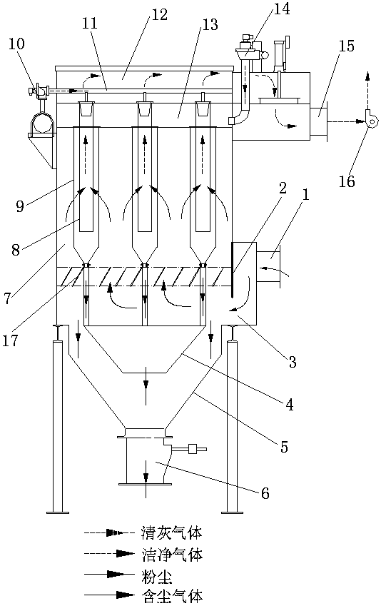
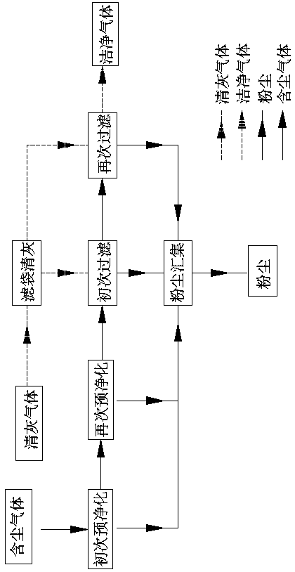
[0045] Such as figure 1 As shown, the dust removal device for ultra-low emission of dusty gas includes air inlet 1, wind deflector 2, settling chamber 3, dust hopper, filter chamber 7, clean air chamber, inner blowing device 10, and outer blowing device 14. The air outlet 15, the exhaust fan 16, the air inlet 1 and the settling chamber 3 are connected, the air guide plate 2 is set between the air inlet 1 and the settling chamber 3, and the ash bucket is set under the settling chamber 3, and the ash bucket is divided into inner The ash hopper 4 and the outer ash hopper 5 have two layers inside and outside, and there is a gap between the inner and outer ash hoppers. The lower part of the outer ash bucket 5 is equipped with an air lock and ash discharge valve 6, the filter chamber 7 is located above the settling chamber 3 and the two are connected, the connecti...


PUM

PropertyMeasurementUnit
particle diameteraaaaaaaaaa

Abstract

The invention discloses a dedusting method and device for achieving ultralow emissions of dusty gas. The dedusting device comprises an air inlet, an air guide plate, a settling room, dust deposition buckets, a filtering room, gas purifying rooms, an inner blowing device, an outer blowing device, an air outlet and an exhaust blower. The air guide plate is arranged between the air inlet and the settling room, the inner dust deposition bucket and the outer dust deposition bucket are arranged below the settling room, and the dust deposition buckets are communicated with the settling room. The filtering room is located above the settling room, a kinetic energy losing device is arranged between the filtering room and the settling room, the gas purifying rooms are arranged above the filtering room, and a blowing pipe is arranged in the upper gas purifying room. The inner blowing device and the outer blowing device are arranged outside the gas purifying rooms, the inner blowing device is communicated with the blowing pipe, and the outer blowing device is communicated with the lower gas purifying room. Sleeve type filtering bags are arranged in the filtering room, the inner sleeve type filtering bag and the outer sleeve type filtering bag are communicated with the inner dust deposition bucket and the outer dust deposition bucket respectively, the upper end of the inner sleeve type filtering bag and the upper end of the outer sleeve type filtering bag are arranged in the upper gas purifying room and the lower gas purifying room respectively, the upper gas purifying room is communicated with the air outlet, and the exhauster blower is arranged on the air outlet. The dedusting device has the advantages of being compact in structure, low in operation cost and high in adaptability, and ultralow emissions of dust can be achieved.

Description

technical field [0001] The invention relates to the technical field of treating atmospheric particle pollutants, which purifies waste gas and flue gas containing particle pollution, and specifically relates to a dust removal method and device for ultra-low emission of dust-containing gas. Background technique [0002] In recent years, the problem of PM2.5 has aroused people's high attention to the control of atmospheric particulate matter pollution. The discharge of gases containing various dusts into the atmosphere is the main form of atmospheric particulate matter pollution, and its treatment is urgent. The method usually used is to contain The dusty gas is introduced into various types of dust collectors to separate the dust from the gas into solid, and the resulting purified gas is discharged to the atmosphere, and the dust is recovered. [0003] There are many types of dust collectors, mainly including: gravity dust collectors, inertial dust collectors, cyclone dust col...

Claims


Application Information

Patent Timeline
Patent Type & Authority Applications(China)
IPC IPC(8): B01D50/00
CPCB01D50/20Y02A50/2351
Inventor 李慧颜世峰时建唐照岭李峰辛生业
Owner 泰安中意重型工业设备有限公司
Why Eureka
Try Eureka