Microporous layer structure of fuel cell, preparation method thereof and anode assembly of fuel cell
A fuel cell and microporous layer technology, applied in battery electrodes, fuel cell additives, electrolyte treatment of solid electrolyte cells, etc., can solve problems such as affecting fuel cell performance, numerous parameters, and unfavorable mass production.
- Summary
- Abstract
- Description
- Claims
- Application Information
AI Technical Summary
Problems solved by technology
Method used
Image
Examples
preparation example Construction
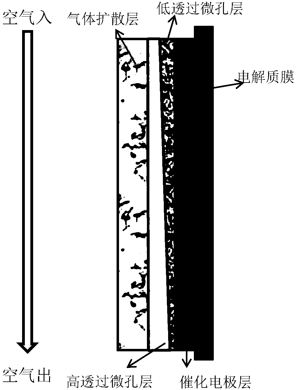
[0032] The present invention also provides a preparation method of the microporous layer structure of the fuel cell, comprising the following steps:
[0033] A), prepare the first slurry mixture and the second slurry mixture, the first slurry mixture and the second slurry mixture are composed of carbon powder, binder, dispersant and solvent, the first slurry mixture one size mixture has a higher water vapor permeability than the second size mixture;
[0034] B), coating the first slurry mixture on the surface of the hydrophobically treated gas diffusion layer, obtaining a microporous layer with high water vapor permeability after heat treatment, and then coating the second slurry mixture to obtain a microporous layer with low water vapor permeability Hole layer;
[0035] Or coat the second slurry mixture on the surface of the hydrophobically treated gas diffusion layer, obtain a microporous layer with low water vapor permeability after heat treatment, and then coat the first ...
Embodiment 1
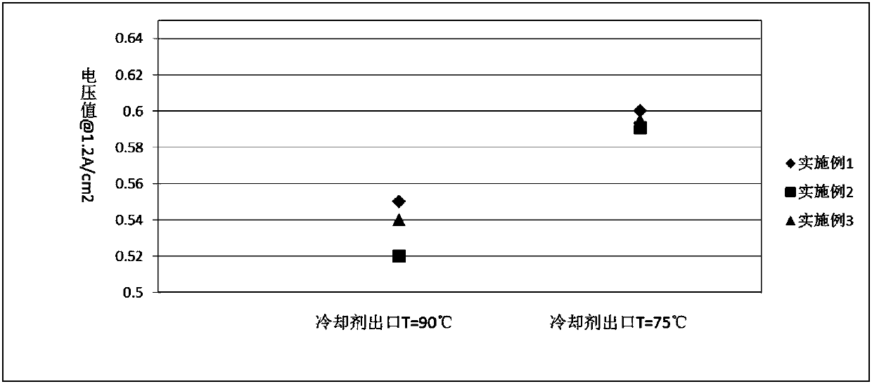
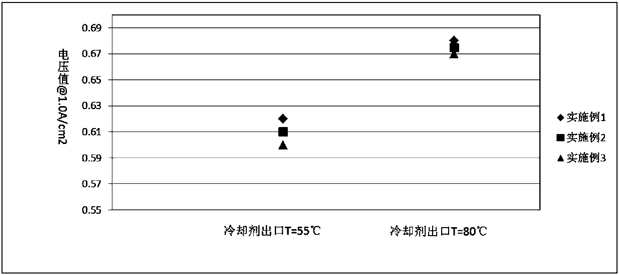
[0043] Use carbon powder A, polytetrafluoroethylene emulsion, deionized water and surfactant to form the first dispersion liquid, perform ultrasonic dispersion and mechanical stirring to form a uniform slurry; coat the above slurry on one side of the gas diffusion layer , the coating tool is a coating machine using a scraper, and the thickness gradient along the air inlet to the air outlet is formed by changing the height of both ends of the scraper. Here, the scraper on the air inlet side is lower than the air outlet side, and the coating on the inlet side The thickness of the slurry is smaller than that of the outlet side, and after heat treatment, the first layer of highly water-permeable microporous layer is formed. The microporous layer has a thickness gradient distribution along the air inlet to the outlet. The thickness of the inlet is 10 μm, and the thickness of the outlet is 30 μm. ;
[0044] Using the second dispersion composed of carbon powder B, polytetrafluoroethy...
Embodiment 2
[0046] Use carbon powder A, polytetrafluoroethylene emulsion, deionized water and surfactant to form the first dispersion liquid, carry out ultrasonic dispersion and mechanical stirring to form a uniform microporous layer slurry; apply this slurry on the gas diffusion layer On one side, the coating tool is a coating machine using a scraper. Here, the scraper on the air inlet side is at the same height as the air outlet side, and after heat treatment, a highly water-permeable microporous layer with uniform thickness is formed. The thickness of the microporous layer is equal to the total thickness of the two microporous layers in Example 1 of 40 μm.
PUM
| Property | Measurement | Unit |
|---|---|---|
| Thickness | aaaaa | aaaaa |
| Thickness | aaaaa | aaaaa |
| Particle size | aaaaa | aaaaa |
Abstract
Description
Claims
Application Information
 - R&D
- Intellectual Property
- Life Sciences
- Materials
- Tech Scout
- Unparalleled Data Quality
- Higher Quality Content
- 60% Fewer Hallucinations
Browse by: Latest US Patents, China's latest patents, Technical Efficacy Thesaurus, Application Domain, Technology Topic, Popular Technical Reports.
© 2025 PatSnap. All rights reserved.Legal|Privacy policy|Modern Slavery Act Transparency Statement|Sitemap|About US| Contact US: help@patsnap.com


