A kind of microporous layer structure of fuel cell, its preparation method and fuel cell cathode assembly

A technology of electrode components and fuel cell membranes, which is applied in the direction of battery electrodes, fuel cell additives, electrolyte treatment of solid electrolyte cells, etc., and can solve the problems of poor improvement of fuel cell water management, unfavorable mass production, and various parameters.

Active Publication Date: 2021-04-09
CRRC QINGDAO SIFANG CO LTD
View PDF7 Cites 0 Cited by
  • Summary
  • Abstract
  • Description
  • Claims
  • Application Information

AI Technical Summary

Problems solved by technology

[0007] The above-mentioned schemes are either complicated in preparation process and have many parameters to be controlled, which is not conducive to mass production, or the effect of improving the water management of the fuel cell is not good, which in turn affects the performance of the fuel cell

Method used


Image

  • A kind of microporous layer structure of fuel cell, its preparation method and fuel cell cathode assembly
  • A kind of microporous layer structure of fuel cell, its preparation method and fuel cell cathode assembly
  • A kind of microporous layer structure of fuel cell, its preparation method and fuel cell cathode assembly

Examples


preparation example Construction

[0032] The present invention also provides a preparation method of the microporous layer structure of the fuel cell, comprising the following steps:

[0033] A), prepare the first slurry mixture and the second slurry mixture, the first slurry mixture and the second slurry mixture are composed of carbon powder, binder, dispersant and solvent, the first slurry mixture one size mixture has a higher water vapor permeability than the second size mixture;

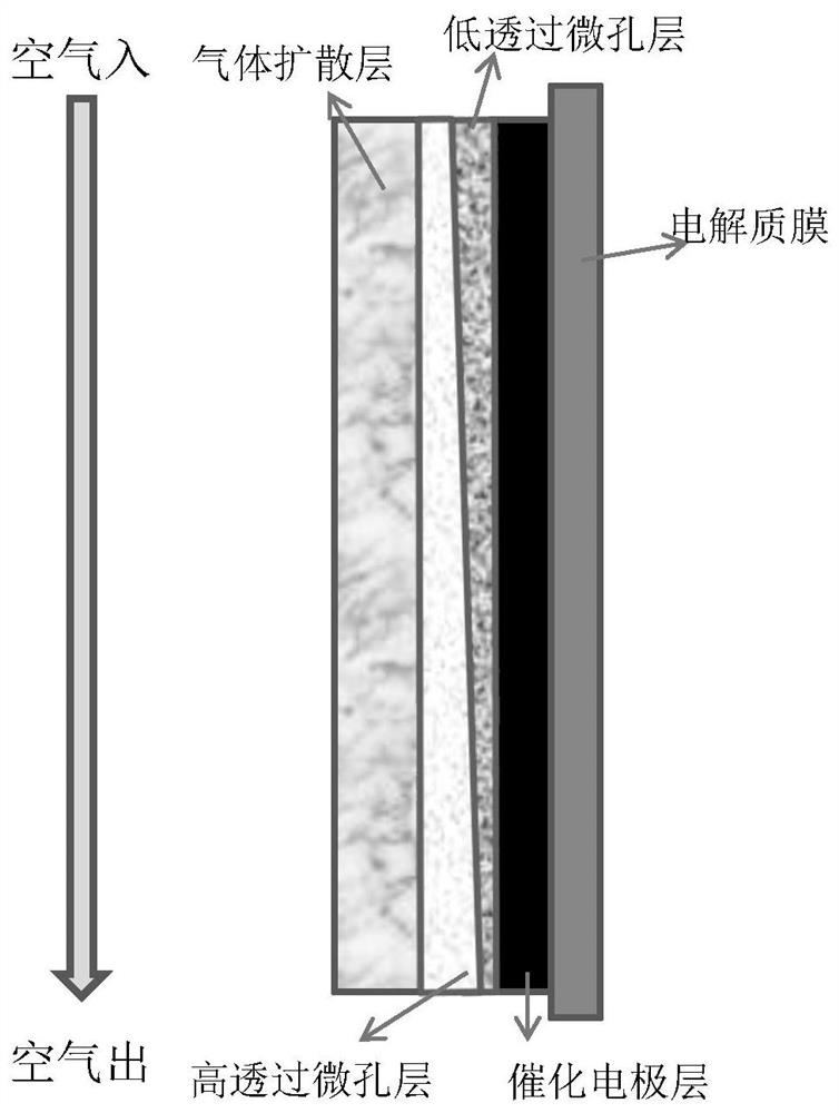
[0034] B), coating the first slurry mixture on the surface of the hydrophobically treated gas diffusion layer, obtaining a microporous layer with high water vapor permeability after heat treatment, and then coating the second slurry mixture to obtain a microporous layer with low water vapor permeability Hole layer;

[0035] Or coat the second slurry mixture on the surface of the hydrophobically treated gas diffusion layer, obtain a microporous layer with low water vapor permeability after heat treatment, and then coat the first ...

Embodiment 1

[0043] Use carbon powder A, polytetrafluoroethylene emulsion, deionized water and surfactant to form the first dispersion liquid, perform ultrasonic dispersion and mechanical stirring to form a uniform slurry; coat the above slurry on one side of the gas diffusion layer , the coating tool is a coating machine using a scraper, and the thickness gradient along the air inlet to the air outlet is formed by changing the height of both ends of the scraper. Here, the scraper on the air inlet side is lower than the air outlet side, and the coating on the inlet side The thickness of the slurry is smaller than that of the outlet side, and after heat treatment, the first layer of highly water-permeable microporous layer is formed. The microporous layer has a thickness gradient distribution along the air inlet to the outlet. The thickness of the inlet is 10 μm, and the thickness of the outlet is 30 μm. ;

[0044] Using the second dispersion composed of carbon powder B, polytetrafluoroethy...

Embodiment 2

[0046] Use carbon powder A, polytetrafluoroethylene emulsion, deionized water and surfactant to form the first dispersion liquid, carry out ultrasonic dispersion and mechanical stirring to form a uniform microporous layer slurry; apply this slurry on the gas diffusion layer On one side, the coating tool is a coating machine using a scraper. Here, the scraper on the air inlet side is at the same height as the air outlet side, and after heat treatment, a highly water-permeable microporous layer with uniform thickness is formed. The thickness of the microporous layer is equal to the total thickness of the two microporous layers in Example 1 of 40 μm.


PUM

PropertyMeasurementUnit
thicknessaaaaaaaaaa
thicknessaaaaaaaaaa
particle diameteraaaaaaaaaa

Abstract

The invention provides a microporous layer structure of a fuel cell, which comprises: a microporous layer with high water vapor permeability and a microporous layer with low water vapor permeability arranged sequentially; The thickness of the air permeable microporous layer increases, the thickness of the low water vapor permeable microporous layer decreases, and the total thickness of the microporous layer structure remains the same; at the air inlet, the thickness of the high water vapor permeable microporous layer is greater than The thickness of the microporous layer with low water vapor permeability, at the air outlet, the thickness of the microporous layer with high water vapor permeability is smaller than the thickness of the microporous layer with low water vapor permeability. The application also provides the preparation method of the microporous layer structure and the membrane electrode assembly of the fuel cell. The fuel cell microporous layer structure provided by the application can balance the water content in the gas inlet and outlet regions of the fuel cell, and finally improve the stability of the fuel cell under various temperatures and humidity, and improve the durability and other functions.

Description

technical field [0001] The invention relates to the technical field of fuel cells, in particular to a microporous layer structure of a fuel cell, a preparation method thereof and a fuel cell cathode assembly. Background technique [0002] Due to the advantages of high energy conversion efficiency, low emission and no pollution, fuel cells have broad prospects for development in the fields of transportation, backup power, and distributed power stations. A typical fuel cell cell consists of an electrolyte membrane (typically a proton exchange membrane), catalytic electrodes for the cathode and anode, a gas diffusion layer, and bipolar plates. Gas diffusion media in fuel cells typically consist of a conductive porous substrate such as carbon fiber paper or carbon cloth, with a microporous layer attached to it. The microporous layer usually includes carbon powder and hydrophobic fluoropolymer, which plays a role in drainage and ventilation and enhances electron transport capabi...

Claims


Application Information

Patent Timeline
Patent Type & Authority Patents(China)
IPC IPC(8): H01M4/86H01M4/88H01M8/04291
CPCH01M4/861H01M4/8878H01M8/04291Y02E60/50
Inventor 万年坊梁建英李克雷张文超张旭
Owner CRRC QINGDAO SIFANG CO LTD
Why Eureka
Try Eureka