Light source system and projection equipment

A light source system and light source technology, applied in the field of optics, can solve problems such as low light utilization efficiency, achieve the effect of improving light utilization rate and avoiding light loss

Inactive Publication Date: 2018-02-16
APPOTRONICS CORP LTD
View PDF10 Cites 24 Cited by
  • Summary
  • Abstract
  • Description
  • Claims
  • Application Information

AI Technical Summary

Problems solved by technology

[0014] In view of this, the present invention provides a light source system and projection equipment to solve the problem of low light utilization efficiency of red light or other colored light emitted by supplementary light sources including red supplementary light sources in the prior art

Method used


Image

  • Light source system and projection equipment
  • Light source system and projection equipment
  • Light source system and projection equipment

Examples


Embodiment 1

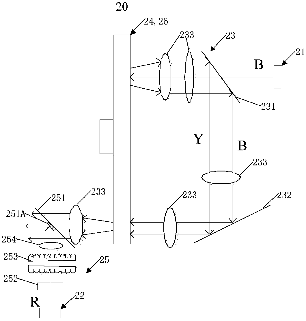
[0057] This embodiment provides a light source system 20, such as figure 2 As shown, the light source system 20 includes two light sources, respectively an excitation light source 21 and a first supplementary light source 22 , and also includes a first light guide assembly 23 , a wavelength conversion device 24 , and a second light guide assembly 25 . In this embodiment, the wavelength conversion device is a reflective color wheel 24 (such as a wavelength conversion layer directly coated on a reflective substrate) as an example, of course, the wavelength conversion device may also be a transmission wavelength conversion device (such as including a transparent substrate and a wavelength conversion material doped inside the transparent substrate). The wavelength conversion material includes but not limited to phosphor powder, quantum dot material and the like. The wavelength conversion layer is a layer of wavelength conversion material or a diaphragm formed by sintering the wa...

Embodiment 2

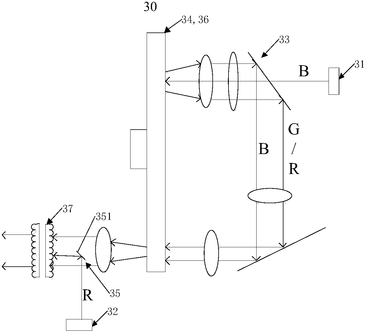
[0065] This embodiment provides another light source system 30, such as image 3 As shown, the light source system 30 and figure 2 The main difference of the light source system 20 shown is the arrangement of the second light guide assembly 35. Specifically, compared with Embodiment 1, the second light guide assembly 35 is not located between the selective optical component 351 and the first supplementary light source 32. A scattering component and a light homogenizing component are arranged between them, and further, a light homogenizing device 37 is arranged on the same exit channel from which the first supplementary light and the received light exit. The above-mentioned light source system 30 provided in this embodiment will be described below with a specific example, assuming that the excitation light emitted by the excitation light source 31 is blue excitation light B, and the first supplementary light emitted by the first supplementary light source 32 is red light R, T...

Embodiment 3

[0067] This embodiment provides another light source system 40, such as Figure 6 As shown, the light source system 40 and image 3 The main difference of the light source system 30 shown is that a first supplementary light source 42' is added, specifically, the first supplementary light source 42 and the first supplementary light source 42' are arranged on the same side of the selective optical component 451, and the first supplementary light source 42' The light source 42' and the first supplementary light source 42 are located on both sides of the light-splitting element 455 included in the second light guide assembly 45. One of them is transmitted and reflected by the other and exits to the selective optical component 451 from the same optical path. Therefore, even if two first supplementary light sources are provided, the area of ​​the incident area corresponding to all the first supplementary light sources of the selective optical component 451 does not need to be Corresp...


PUM


Abstract

The invention provides a light source system and projection equipment. The light source system comprises an exciting light source, a first supplementing light source, a first light guiding assembly, awavelength conversion device and a second light guiding assembly, wherein the exciting light source is used for emitting exciting light; the first supplementing light source is used for emitting first supplementing light; the first light guiding assembly is used for guiding exciting light to the wavelength conversion device; The wavelength conversion device is used for converting exciting light into excited light and transmitting the excited light to the first light guiding assembly; the first light guiding assembly is further used for guiding excited light so that the excited light is transmitted to the second light guiding assembly; at least a part of components of the second light guiding assembly are arranged on the light path of the excited light after emitted from the first light guiding assembly; and the second light guiding assembly is used for guiding one or two of excited light and first supplementing light so that the first supplementing light and at least a part of the excited light are emitted from a same emission passage. The light utilization rate of the first supplementing light can be greatly improved.

Description

technical field [0001] The present invention relates to the field of optical technology, more specifically, to a light source system and projection equipment. Background technique [0002] At present, solid-state light sources have been widely used in general lighting, special lighting and projection display due to their long life and environmental protection. Among them, the white light solid-state light source has great development potential in the field of lighting. [0003] The prior art provides a white light source that uses laser to excite phosphor powder to achieve ultra-high brightness. The white light source uses a blue-violet laser with a wavelength of 440nm-455nm to excite yellow phosphor powder of YAG:Ce material to generate high-efficiency yellow fluorescence. A blue laser with a wavelength of 440nm-470nm is then used to form a blue laser complementary to the yellow fluorescence, and the yellow fluorescence and the blue laser combine to form a white light sour...

Claims


Application Information

Patent Timeline
Patent Type & Authority Applications(China)
IPC IPC(8): G03B21/20
CPCG03B21/2013G03B21/204G03B21/2066G03B21/2073G03B33/08G03B21/20G02B26/008G03B21/2033G03B21/206
Inventor 胡飞郭祖强李屹
Owner APPOTRONICS CORP LTD
Why Eureka
Try Eureka