
Precision control device and method for laser indirect impact micro molding

A precision control and micro-forming technology, which is applied in the field of laser processing and manufacturing and advanced mechanical manufacturing of micron-level parts, can solve the problems of inability to process, friction between the punch and the die, and insufficient forming quality, so as to save time and improve work. efficiency effect

Active Publication Date: 2018-02-23
JIANGSU UNIV
View PDF7 Cites 10 Cited by
  • Summary
  • Abstract
  • Description
  • Claims
  • Application Information

AI Technical Summary

Problems solved by technology

However, the device can only achieve single energy field forming, and cannot process some materials that are difficult or impossible to form by conventional laser shock microforming methods;
[0005] The Chinese patent with the publication number CN104162595A adopts ultrasonic vibration-assisted foil plate micro-punching forming device to solve the problem that the ordinary punching and forming quality of the existing precision foil plate is not high enough, the section quality and shape and position tolerance cannot meet the requirements, and the mold is severely worn and used. Low service life and other problems, the foil plate also completes the fine blanking and forming of the foil plate in order to solve the bottleneck problems such as the difficulty of energy transfer and the difficulty of realizing the vibration system in the vibration-assisted forming of large-sized components
However, this device cannot realize multi-station processing, and uses the micro-rigid punch and die to realize the micro-plastic forming process, and there are still some problems, such as the punch is easily damaged, the punch and the die are difficult to align, the punch and the die There are defects such as friction between the molds

Method used


Image

  • Precision control device and method for laser indirect impact micro molding
  • Precision control device and method for laser indirect impact micro molding
  • Precision control device and method for laser indirect impact micro molding

Examples


Embodiment Construction

[0043] The present invention will be further described below in conjunction with the accompanying drawings and the mold with 4 rows and 4 columns of array cavities, but the protection scope of the present invention is not limited thereto.

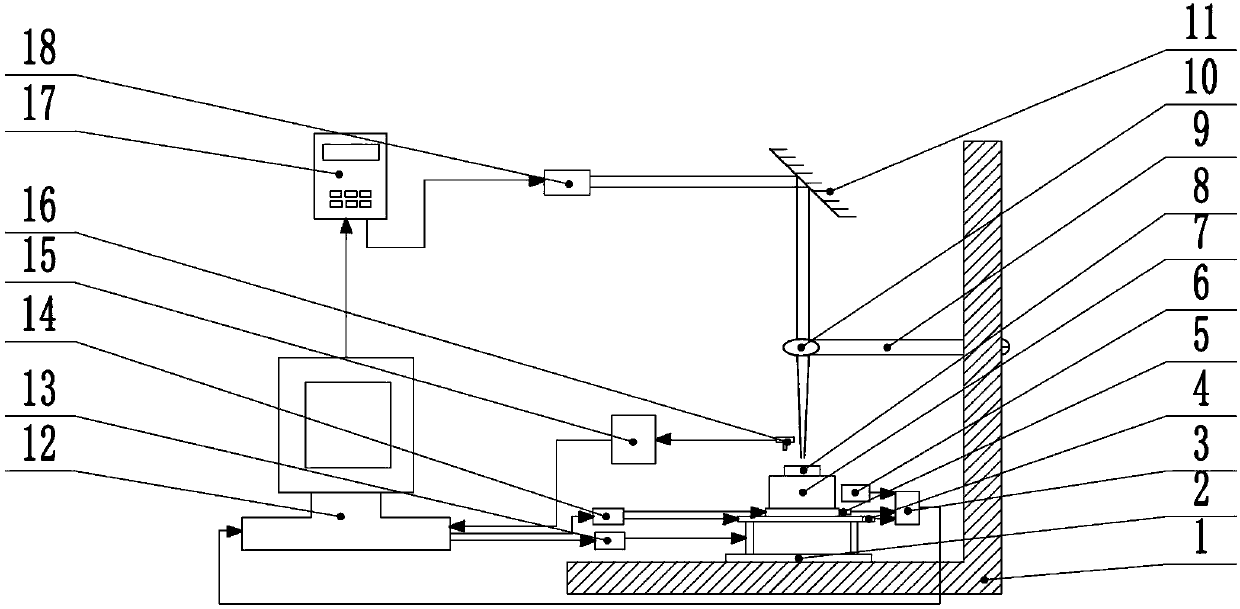
[0044] A precision control device for laser indirect impact micro-forming according to the present invention combined with the attached figure 1 As shown, including laser loading system, ultrasonic vibration system, spot-mold cavity centering component, workpiece component and control system;

[0045] combined with figure 1 As shown, the laser loading system includes an L-shaped base 1, a pulse laser 18, a lens adjustment arm 9, an adjustable focus lens 10, and a total reflection mirror 11; the laser beam emitted by the pulse laser 18 is reflected to the Focus on the adjustable focusing lens 10, and the focused laser beam is irradiated to the debugging light spot—the center position of the mold cavity centering component after debugging; t...


PUM

PropertyMeasurementUnit
Thicknessaaaaaaaaaa
Thicknessaaaaaaaaaa

Abstract

The invention provides a precision control device and method for laser indirect impact micro molding, and relates to the technical field of laser machining of micro electro mechanical system parts. The precision control device comprises a laser loading system, an ultrasonic vibration system, a debugging optical light spot-mold cavity centering assembly, a workpiece assembly and a control system. By means of the precision control device, the impact force of a pulse laser is adopted as an energy source, meanwhile, ultrasonic vibration is applied to a mold and a workpiece, the molding limitationand the molding quality of the workpiece are improved, and the precision control device is suitable for materials which are difficult to mold or cannot be molded by using a conventional laser impact micro molding method. Meanwhile, the movement situation of a motor can be monitored and fed back through a coder, the movement situations of a front-back platform and a left-right platform can be monitored and fed back through a grating ruler displacement sensor, and accordingly the precision of a three-dimensional movable platform can be improved. The precision control device is suitable for achieving large-area mold molding and multi-working-station laser impact molding, so that the workpiece precisely duplicates the morphology of the mold, or batch molding of the workpiece is completed simultaneously, and thus the working efficiency is improved.

Description

technical field [0001] The invention belongs to the field of laser processing and manufacturing and mechanical advanced manufacturing of micron-level parts, in particular to a precision control device and method for laser indirect impact micro-forming. Background technique [0002] With the rapid development of modern manufacturing industry, advanced manufacturing industry has received more and more attention. Micro Electro Mechanical System (MEMS) and Micro System Technology (MST) are widely used in aerospace, precision instruments, automobile industry, biological The medical field, microelectronics and many other civilian and military fields are favored. The miniaturization of products has become a development trend in the manufacturing industry. Therefore, the research on thin plate microforming has received extensive attention. Some lightweight metal materials, such as magnesium alloy, aluminum alloy, titanium alloy, etc., have become the objects of extensive research ...

Claims


Application Information

Patent Timeline
IPC IPC(8): B21D26/00
CPCB21D26/00
Inventor 刘会霞刘菲孙凯蒋晨坤王霄
Owner JIANGSU UNIV
Learn More