
High-precision positioning method for LED chip array arrangement

An LED chip and array arrangement technology, applied in electrical components, circuits, semiconductor devices, etc., can solve the problems of chip integration failure, high investment cost, affecting the chip integration yield rate, etc., to ensure the uniformity and consistency of color temperature. performance, and the effect of improving the delivery rate

Active Publication Date: 2018-02-23
XIANGNENG HUALEI OPTOELECTRONICS
View PDF7 Cites 3 Cited by
  • Summary
  • Abstract
  • Description
  • Claims
  • Application Information

AI Technical Summary

Problems solved by technology

In this way, for a large-area chip arrangement, especially for a small-sized CSP, it is difficult to ensure that the thickness of the encapsulant on the upper part of the LED bare chip and the four side walls is the same, which will directly affect the yield rate of the LED chip package.
[0004] The patent application number 201610261522.6 discloses the light source assembly structure and manufacturing method of the flip-chip LED chip integrated package. It is precisely because the positioning accuracy of the chip array arrangement is not high that the P and N electrodes of the chip are caused by the position error of the interconnection. Integration failure, which directly affects the yield rate of chip integration
[0005] At present, there are high-precision chip layout equipment that can improve the accuracy to within ±10um, but the cost of this kind of chip layout equipment is as high as millions of yuan, and the investment cost is too high

Method used


Image

  • High-precision positioning method for LED chip array arrangement
  • High-precision positioning method for LED chip array arrangement
  • High-precision positioning method for LED chip array arrangement

Examples


Embodiment 1

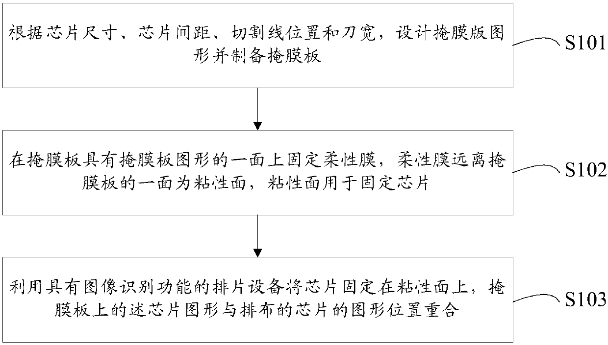
[0045]The existing ordinary chip placement equipment has a low accuracy of only ±30um in chip positioning; while high-precision chip placement equipment can improve the accuracy to ±10um, but the price of high-precision chip placement equipment is as high as nearly one million yuan. Replacement of high-precision chip placement equipment Equipment saving investment is too high. In order to solve the above problems, this embodiment provides a high-precision positioning method for LED chip arrays, which can improve the positioning accuracy of the chips to below ±10um by using existing common chip arrangement equipment.

[0046] figure 1 A process flow chart of the high-precision positioning method of the LED chip array in this embodiment is given. See figure 1 , the positioning method, including:

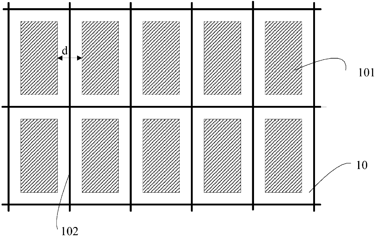
[0047] Step S101: figure 2 A top view schematic diagram of step S101 in this embodiment is given, and a mask pattern is designed and a mask plate is made according to the chip siz...

Embodiment 2

[0056] Figure 6 A process flow chart of the high-precision positioning method of the LED chip array in this embodiment is given. See Figure 6 , the positioning method, including:

[0057] Step S201: Figure 7 A top view schematic diagram of step S201 in this embodiment is given, and a mask pattern is designed and a mask plate is made according to the chip size, the chip spacing d, the position of the cutting line 102 and the knife width.

[0058] Figure 8 A cross-sectional schematic diagram of step S201 in this embodiment is given, please refer to Figure 7 and Figure 8 , forming a light blocking layer 10 on the glass substrate 20, using photolithography technology to etch the light blocking layer 10 to form a mask pattern, the mask pattern includes a plurality of chip patterns 101 arranged in an array, and the chip pattern 101 The light blocking layer 10 is etched away.

[0059] Need to explain is, Figure 7 There are 10 chip patterns 101 in the mask plate given i...

Embodiment 3

[0066] figure 1 The process flow chart of the high-precision positioning method of the LED chip array in this embodiment is given, please refer to Figure 11 , the present embodiment provides a high-precision positioning method for an LED chip array, including:

[0067] Step S301: Design a mask pattern and make a mask plate according to the chip size, chip pitch, dicing line position and knife width. The mask pattern includes a plurality of chip patterns arranged in an array.

[0068] Step S302: Fix the flexible film on the side of the mask plate having the pattern of the mask plate, the side of the flexible film 2 away from the mask plate is an adhesive surface, and the adhesive surface is used to fix the chip.

[0069] It should be noted that the flexible film in the present invention is a transparent film with a temperature resistance greater than 150°C. The flexible film can be a double-sided adhesive film or a single-sided adhesive film. If the flexible film is a double...


PUM


Abstract

The present application provides a high-precision positioning method for LED chip array arrangement. The method includes the following steps that: a mask layout is designed according to chip size, a chip spacing, a cutting line position and knife width, and a mask plate is manufactured, wherein the mask layout contains a plurality of arrayed chip patterns; a flexible film is fixed onto one side ofthe mask plate, wherein the one side of the mask plate is provided with the mask layout, the flexible film is a transparent thin film resistant to temperatures greater than 150 DEG C, and a surface of the flexible film, which is far away from the mask plate, is an adhesive surface, the adhesive surface is used for fixing the chips; and a chip arrangement device with an image identification function is utilized to fix the chips on the adhesive surface, and the chip patterns on the mask plate are overlapped with the patterns of the arranged chips. With the method adopted, the accuracy of the arrangement spacing of the chips can be improved, the uniformity of the thickness of the encapsulant of the CSP (Chip Scale Package) chips and the uniformity of the color temperature of the CSP chips can be improved, and the yield of LED chip package can be improved.

Description

technical field [0001] The invention belongs to the technical field of LEDs, and in particular relates to a high-precision positioning method for array arrangement of LED chips. Background technique [0002] A light-emitting diode (Light-Emitting Diode, LED) is a semiconductor electronic device that converts electrical energy into light energy. Substrate-less chip-scale packaging (Chip Scale Package, CSP) of flip-chip LED is a new type of packaging technology for LED chips. Since CSP eliminates the carrier substrate, it reduces the increase in system thermal resistance caused by the carrier substrate. , so that the high-current carrying capacity of the obtained LED chip is further improved, and at the same time, the manufacturing process is shortened and the production cost is reduced, so the market share in the lighting market is getting higher and higher. The patent with application number 201510130969.5 discloses a specific method of encapsulation using CSP technology. ...

Claims


Application Information

Patent Timeline
Patent Type & Authority Applications(China)
IPC IPC(8): H01L33/48H01L21/68
CPCH01L21/682H01L33/48H01L2933/0033
Inventor 王良臣周智斌苗振林季辉许亚兵
Owner XIANGNENG HUALEI OPTOELECTRONICS
Learn More