Robot joint tail end residual vibration restraining method based on input shaper

A robot joint and input shaping technology, applied in manipulators, manufacturing tools, etc., can solve problems affecting the vibration suppression effect of the input shaper, system output time lag, etc., to reduce system time lag, enhance robustness, and reduce sensitivity degree of effect

Active Publication Date: 2018-02-27
SOUTH CHINA UNIV OF TECH
View PDF9 Cites 31 Cited by
  • Summary
  • Abstract
  • Description
  • Claims
  • Application Information

AI Technical Summary

Problems solved by technology

However, there are also many problems in the traditional input shaper, such as the length of the pulse sequence will cause the time lag of the system output; due to the shaping of the reference input, there is an inevitable control error between the actual output and the reference input; in addition, The design of the input shaper depends on the system natural frequency and damping ratio, so the uncertainty of the system parameters will also affect the vibration suppression effect of the input shaper

Method used


Image

  • Robot joint tail end residual vibration restraining method based on input shaper
  • Robot joint tail end residual vibration restraining method based on input shaper
  • Robot joint tail end residual vibration restraining method based on input shaper

Examples


Embodiment

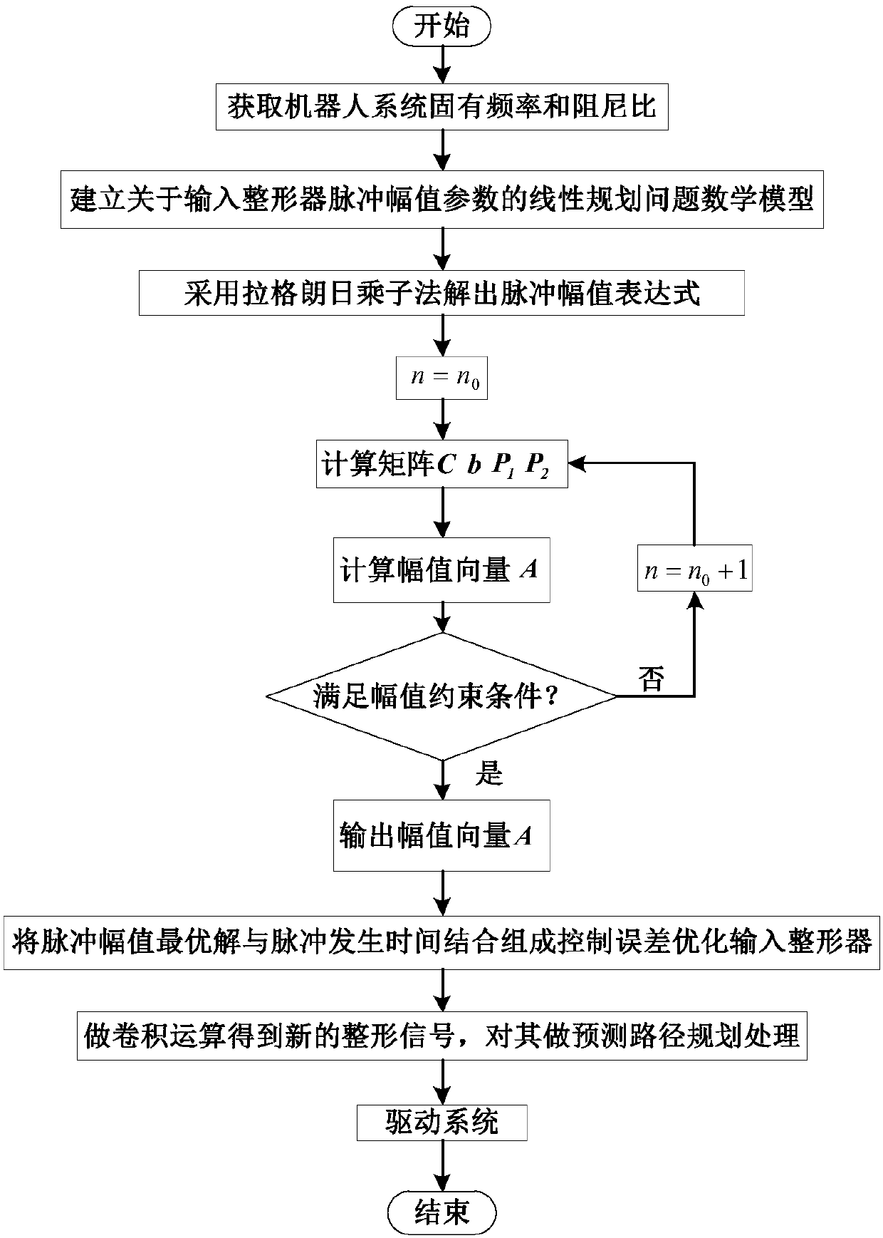
[0062] Such as figure 1 As shown, a method for suppressing residual vibration at the end of a robot joint based on an input shaper includes the following steps:

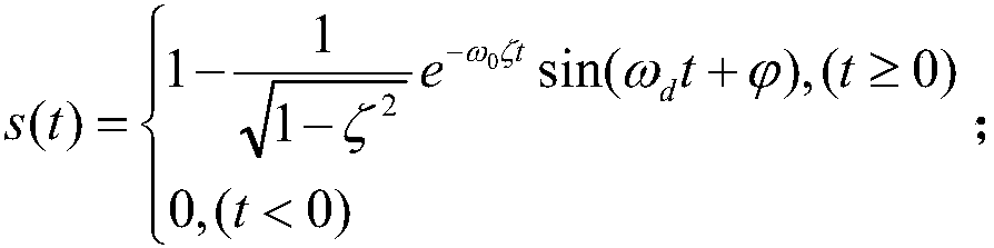
[0063] Step 1: Obtain the undamped natural frequency ω of the robot system 0 and damping ratio ζ;

[0064] Step 2: establishing a linear programming problem mathematical model about the input shaper pulse amplitude parameter;

[0065] Step 3: use the Lagrange multiplier method to solve the pulse amplitude expression, and iteratively obtain the optimal solution of the pulse amplitude;

[0066] Step 4: Combining the optimal solution of the pulse amplitude with the pulse generation time to form a control error optimization input shaper;

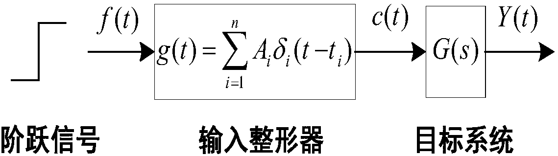
[0067] Step 5: Input the reference signal and control error optimization into the shaper to perform convolution operation to obtain a new shaping signal, and then use the signal to drive the system to suppress the residual vibration at the end of the robot (see figure 2 ).

[006...


PUM


Abstract

The invention discloses a robot joint tail end residual vibration restraining method based an input shaper. The robot joint tail end residual vibration restraining method based the input shaper comprises the steps that firstly, the undamped inherent frequency omega0 and the damping ratio zeta of a robot system are obtained; secondly, a linear programming problem mathematic model about the pulse amplitude parameter of the input shaper is established; thirdly, a pulse amplitude expression is solved through a lagrangian multiplier method, and the optimal solution of the pulse amplitude is workedout through iteration; fourthly, the optimal solution of the pulse amplitude and the pulse generation time are combined to form the control error optimization input shaper; and fifthly, a reference signal and the control error optimization input shaper are subjected to convolution operation, so that a novel shaping signal is obtained, and after a predicted path is planned for the novel shaping signal, the system is driven by the signal to restrain robot tail end residual vibration. According to the robot joint tail end residual vibration restraining method based the input shaper, the robustness of the input shaper is enhanced, and a process control error and a positioning error are minimized; and the predicted path is planned for the shaped signal, and thus the system lag time caused by input shaping is compensated and reduced.

Description

technical field [0001] The invention relates to a method for suppressing residual vibration at the end of a robot joint based on a control error optimized input shaper, and belongs to the technical field of robot vibration control. Background technique [0002] In the automatic assembly and handling process on the industrial production line, the robot end effector is often required to have a strong rapid positioning capability. However, the existence of joint flexible parts in the robot (such as harmonic reducer flexible wheels, J5-axis synchronous belt, etc.) will cause long-term residual vibration of the end effector after the motion stops. This phenomenon occurs when the robot moves at high speed. More obviously, the positioning accuracy and speed of the end effector are greatly reduced, which seriously affects the stability and reliability of the robot control system. [0003] The input shaper is a feed-forward control method that can effectively suppress the residual v...

Claims


Application Information

Patent Timeline
Patent Type & Authority Applications(China)
IPC IPC(8): B25J19/00
CPCB25J19/0091
Inventor 张铁林康宇
Owner SOUTH CHINA UNIV OF TECH
Why Eureka
Try Eureka