Flat heat pipe, manufacturing method and phase change heat storage and release device

A flat heat pipe, heat storage and release technology, applied in heat storage equipment, heat exchanger types, indirect heat exchangers, etc. Compact structure, stable heat storage and release, and short thermal response time

Pending Publication Date: 2018-03-06
北京市天银地热开发有限责任公司
View PDF0 Cites 2 Cited by
  • Summary
  • Abstract
  • Description
  • Claims
  • Application Information

AI Technical Summary

Problems solved by technology

The skeleton of phase change energy storage technology is the heat storage system structure. At present, most heat storage systems mainly use coiled tubes as the main heat exchange structure, which is large in size, large in resistance, and high in cost. Due to the small diameter of the coiled tubes , many elbows, long pipes cause large resistance, and the improvement of thermal performance is not obvious, so optimizing the structure of the heat storage system is also the direction that people have been trying and exploring
[0004] Another aspect of phase change energy storage technology research is phase change heat storage materials. At present, most inorganic phase change materials are corrosive and will suffer from supercooling and phase separation during the phase change process, which severely limits their application in industry. The wide application of organic phase change materials has the advantages of low corrosion, almost no supercooling and phase separation during the phase change process, stable chemical properties, and low price. Utilization, building energy conservation and other fields, organic phase change materials are more widely used
However, organic phase change materials generally have the disadvantage of low thermal conductivity, which makes them have poor heat transfer performance and low utilization rate of stored heat in the application of energy storage systems, thereby reducing the energy efficiency of the system.

Method used


Image

  • Flat heat pipe, manufacturing method and phase change heat storage and release device
  • Flat heat pipe, manufacturing method and phase change heat storage and release device
  • Flat heat pipe, manufacturing method and phase change heat storage and release device

Examples


Embodiment Construction

[0072] In order to facilitate those skilled in the art to understand and realize the present invention, the flat heat pipe, the manufacturing method of the flat heat pipe and the phase change heat storage and release device made of the flat heat pipe according to the present invention will be further described in conjunction with the accompanying drawings and specific embodiments.

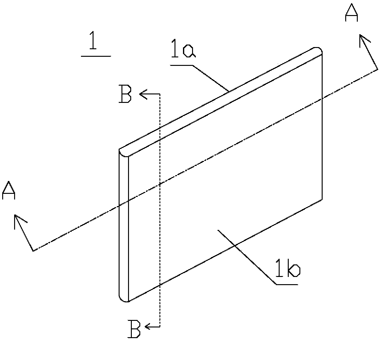
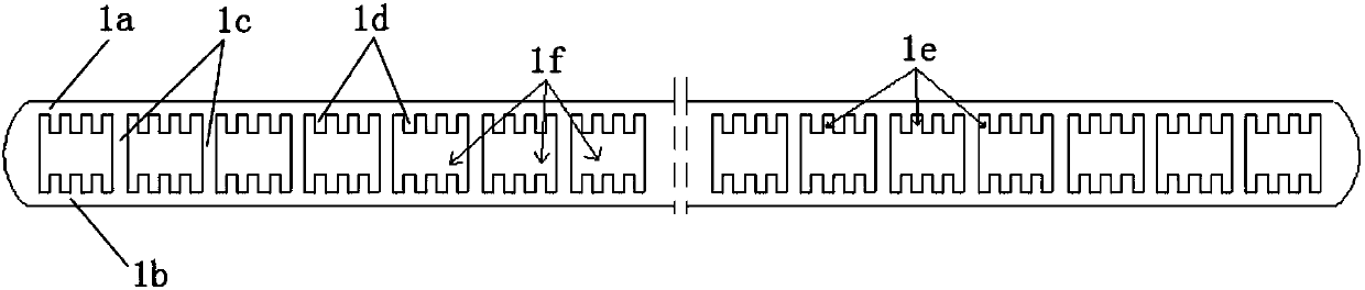
[0073] Such as figure 1 , figure 2 Shown is a flat heat pipe 1, including inner and outer plates 1a, 1b and a grid 1c, the grid 1c is fixedly connected with the inner walls of the inner and outer plates 1a, 1b, and divides the inner cavity of the flat heat pipe into a plurality of interconnected The cavity 1f, the inner walls of the inner and outer plates 1a, 1b are all provided with a plurality of protrusions 1d, and grooves 1e are formed between adjacent protrusions 1d or between the grid 1c and the protrusions 1d.

[0074] Such as figure 2 As shown, both the protrusion 1d and the groove 1e a...


PUM

PropertyMeasurementUnit
Thicknessaaaaaaaaaa

Abstract

The invention provides a flat heat pipe, a manufacturing method and a phase change heat storage and release device. The flat heat pipe comprises an inner side plate, an outer side plate and a grille.The grille is fixedly connected with the inner walls of the inner side plate and the outer side plate, an inner cavity of the flat heat pipe is divided into multiple communicating cavities, the innerwalls of the inner side plate and the outer side plate are provided with multiple protrusions, and a groove is formed between every two adjacent protrusions or formed between the grille and the corresponding protrusion. The phase change heat storage and release device comprises an exchange device, a water pipe and a box body. The exchange device is fixed inside the box body and fixedly connected with the water pipe, the end of the water pipe stretches out of the box body, the water pipe comprises an upper water pipe and a lower water pipe, the upper water pipe is fixedly installed on the upperportion of the exchange device, the lower water pipe is fixedly installed on the lower portion of the exchange device, and the space between the box body and the exchange device is filled with heat storage and release media.

Description

technical field [0001] The invention relates to a heat dissipation element, a method for manufacturing a heat dissipation element and applications thereof, in particular to a flat heat pipe, a method for manufacturing the flat heat pipe, and a phase-change heat storage and release device made using the flat heat pipe. Background technique [0002] At present, for the purpose of energy conservation, emission reduction and environmental protection, the full utilization of conventional energy has received great attention, and heat storage technology is one of the important ways to improve energy utilization efficiency and protect the environment. This technology is mainly used in the fields of solar energy storage, power "peak shaving and valley filling", industrial waste heat and waste heat recovery, etc. Heat storage methods are roughly divided into sensible heat storage, latent heat storage and chemical heat storage. Among them, latent heat storage, that is, phase change he...

Claims


Application Information

Patent Timeline
IPC IPC(8): F28D15/02F28D20/02B21C23/08
CPCF28D15/0233F28D20/021B21C23/085Y02E60/14
Inventor 关云峰程鹏樊洪明闫桂兰彭宏孟文博孙立冬赵耀华
Owner 北京市天银地热开发有限责任公司
Why Eureka
Try Eureka