Phased array identification method and system

An identification method and phased array technology, applied in radio wave measurement systems, radio wave reflection/re-radiation, utilization of re-radiation, etc., can solve problems such as not really proposed, unable to apply information products

Active Publication Date: 2018-03-06
丁贤根
View PDF25 Cites 13 Cited by
  • Summary
  • Abstract
  • Description
  • Claims
  • Application Information

AI Technical Summary

Problems solved by technology

[0014] Although these patent documents have proposed some good solutions from a partial point of view, they have not really proposed the aforementioned: short-distance, micro-power consumption, mic...

Method used


Image

  • Phased array identification method and system
  • Phased array identification method and system
  • Phased array identification method and system

Examples


specific Embodiment approach

[0120] A class of specific embodiments of the present invention are as follows:

[0121] 1: Gesture recognition system

specific Embodiment approach 1

[0122] Specific Embodiments 1. Gesture Recognition System

[0123] This embodiment is an illustrative example of the present invention for a gesture recognition system.

[0124] The gesture recognition system is a system for recognizing animal movements, including but not limited to human gesture recognition.

[0125] 1. Method and system description

[0126] A class of specific embodiments of the inventive method includes:

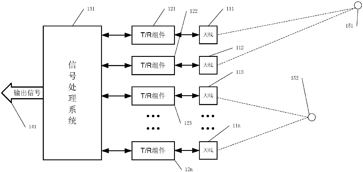
[0127] The step of adjusting the phase of transmitting millimeter waves from the transmitting end of more than one T / R component and more than one antenna, so that the focusing azimuth formed by emitting millimeter waves scans the sub-field and / or the whole field.

[0128] The step of controlling more than one T / R component and the receiving end of more than one antenna to receive more than one detected object to reflect and emit millimeter waves.

[0129] A step of calculating detection data of one or more detected objects based on millimeter waves re...

specific Embodiment approach 2

[0248] Specific implementation mode two, automobile anti-collision system

[0249] This embodiment is an illustrative example of the present invention for an automobile collision avoidance system.

[0250] Automobile anti-collision system is a kind of anti-collision system used on land vehicles, including but not limited to automobiles. Compared with the previous embodiments, the similarities of this embodiment will not be repeated, and the main differences of the system are as follows:

[0251] 1. Method and system differentiation description

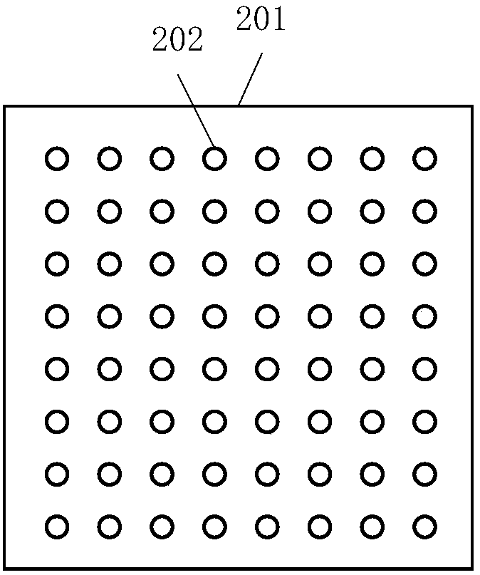
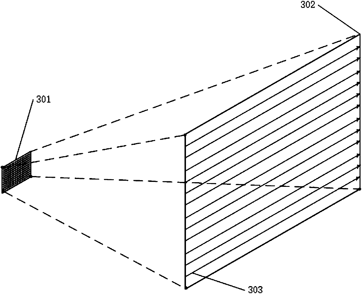
[0252] The phased array T / R component and / or the number of antennas in the phased array antenna array is set to 4-512. The phased array antenna array is arranged in a one-dimensional linear arrangement, including but not limited to two parallel lines, triangular, rectangular and polygonal arrangements, to form a planar detection field. The multiple phased array T / R components and the phased array antenna array are set to: the wavele...


PUM


Abstract

The invention provides a phased array identification method and system to realize object motion recognition including gesture recognition, automotive anti-collision recognition, collision avoidance and anti-attack recognition of an unmanned aerial vehicle, and smart missile and ship collision prevention recognition. The system is composed of a phased array antenna array, a phased array T/R assembly array and a signal processing system. A phased array millimeter wave is emitted and a millimeter wave reflected by a detected object is received; and calculation is carried out to determine a spacecoordinate of the detected object. The calculation includes one based on an artificial intelligence algorithm and is implemented by steps of target recognition, correction, searching, tracking, and gazing and the like. The signal processing system includes a Von's computer, a non-Von's computer, a neural network, and an artificial intelligence system. The phased array identification system can bemanufactured into a two-in-one MMIC chip and a three-in-one SoC MMIC chip.

Description

technical field [0001] The present invention relates to the subfield of intelligent sensors in information technology, in particular to active phased array sensing technology, in particular to active phased array gesture recognition and moving object recognition, and specifically to a phased array recognition method and system. Background technique [0002] Active Electronically Scanned Array (AESA) detection technology is usually used in military and meteorological aspects. Active Electronically Scanned Array radar is mainly used for long-distance detection of aircraft, missiles, clouds and other targets. In these aspects, both products and applications are relatively mature. [0003] The wavelength of millimeter wave (MilliMeter Wave, MMW for short) is usually between 1mm and 10mm; however, with the development of integrated circuit technology, the process and technology of monolithic microwave integrated circuit (MMIC for short) have made The wavelength extends down to 0...

Claims


Application Information

Patent Timeline
IPC IPC(8): G01S13/02
CPCG01S13/02
Inventor 丁贤根
Owner 丁贤根
Why Eureka
Try Eureka