Methods for surface preparation of sputtering target
一种溅射靶、喷射喷嘴的技术,应用在抛光溅射靶,处理溅射靶领域,能够解决花费时间和金钱等问题
- Summary
- Abstract
- Description
- Claims
- Application Information
AI Technical Summary
Problems solved by technology
Method used
Image
Examples
Embodiment 1
[0054] Embodiment 1: hot-pressed ruthenium (Ru) target
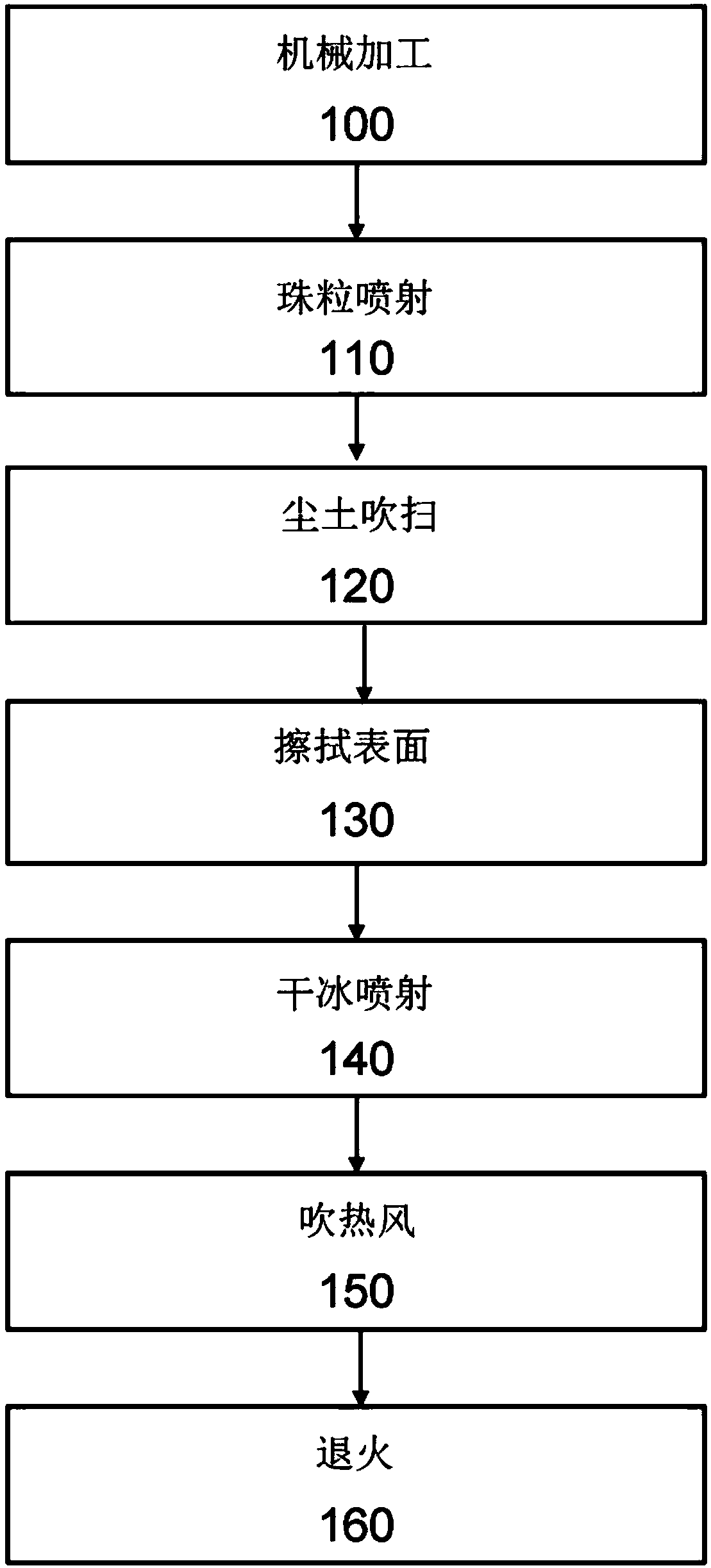
[0055] A ruthenium (Ru) sputtering target with a diameter of 165 mm and a thickness of 3.8 mm was sintered, followed by machining and mechanical grinding steps. This was followed by bead blasting with spherical zirconia beads.
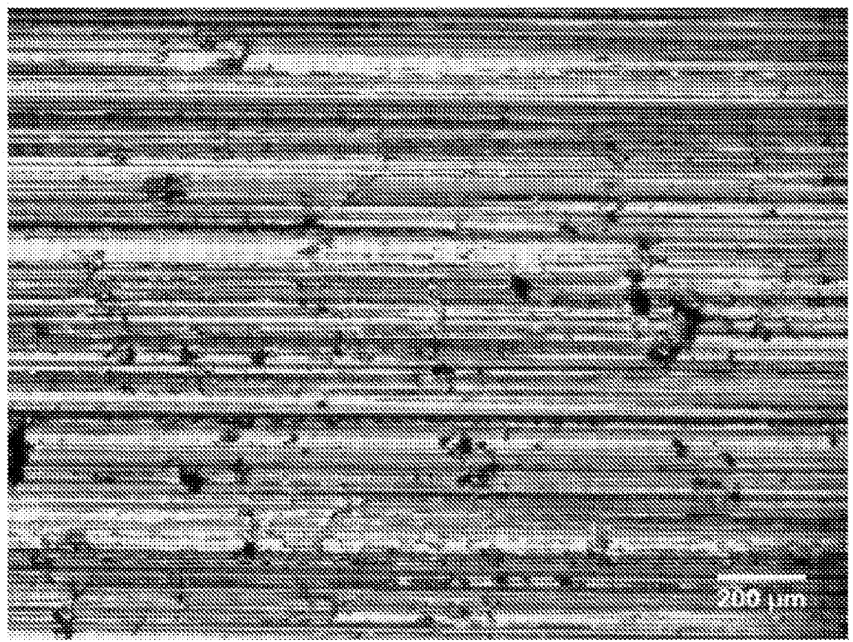
[0056] Figure 2A is an optical micrograph of the sputtering target surface after machining, ie before bead ejection. Grinding-induced defects such as surface micro-cracks, wear marks, contamination and other surface defects were observed on the ground surface. The surface roughness after grinding is anisotropic. In the direction parallel to the grinding direction, the surface roughness is 3-7 Ra, whereas in the direction transverse to the grinding direction, the surface roughness is 8-12 Ra.
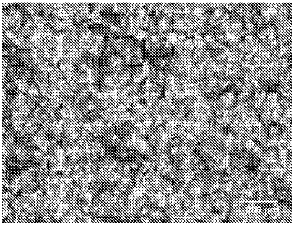
[0057] Figure 2B is an optical micrograph of the sputtering target surface after bead blasting. Grinding-induced defects are overcome by bead jetting. A uniformly clean surface was also observed af...
Embodiment 2
[0063] Embodiment 2: cast iron-boron-cobalt (Fe x co y B 20 )target
[0064] Iron-cobalt-boron (Fe x co y B 20 ) sputtering target followed by a mechanical grinding step followed by bead blasting with zirconia beads.
[0065] Figure 3A is an optical micrograph of the sputtering target surface after mechanical grinding and before bead jetting. Grinding-induced defects such as surface micro-cracks, wear marks and contamination were observed on the ground surface.
[0066] Figure 3B is an optical micrograph of the sputtering target surface after bead blasting, dust blowing and surface wiping. Grinding-induced defects are overcome by bead jetting. A uniform and clean surface was observed after bead blasting. Fe x co y B 20 Cast sputtering targets of the alloy exhibit high density and high hardness (55-66 HRC). After bead jetting, there were less than 100 particles in the range of 0.1 μm to 1 μm during sputtering. Fe after bead blasting, dust blowing and surface wip...
Embodiment 3
[0067] Example 3: MgO sputtering target
[0068] Magnesia (MgO) sputtering targets with a diameter of 175 mm and a thickness of 5 mm made by sintering were subjected to a mechanical grinding step followed by bead blasting with spherical zirconia beads.
[0069] Figure 4A is the optical micrograph of the machined sputtering target surface. Machining-induced microcracks and aggregated MgO particles were observed. The surface roughness in the direction parallel to the grinding line is 31-37Ra, and the surface roughness in the direction transverse to the grinding line is 35-39Ra.
[0070] Figure 4B is an optical micrograph of the sputtering target surface after bead blasting. The surface roughness becomes isotropic (about 98-126 Ra) in the two crossing directions. Although the surface roughness increased after bead blasting, marks caused by machining were removed by bead blasting. Aggregated and loosely bound particles are also wiped off. This surface structure and charac...
PUM
| Property | Measurement | Unit |
|---|---|---|
| diameter | aaaaa | aaaaa |
| size | aaaaa | aaaaa |
| diameter | aaaaa | aaaaa |
Abstract
Description
Claims
Application Information
 - R&D
- Intellectual Property
- Life Sciences
- Materials
- Tech Scout
- Unparalleled Data Quality
- Higher Quality Content
- 60% Fewer Hallucinations
Browse by: Latest US Patents, China's latest patents, Technical Efficacy Thesaurus, Application Domain, Technology Topic, Popular Technical Reports.
© 2025 PatSnap. All rights reserved.Legal|Privacy policy|Modern Slavery Act Transparency Statement|Sitemap|About US| Contact US: help@patsnap.com


