Copper and steel composite pipe and preparation method thereof

A copper-steel composite and composite pipe technology, which is applied in the direction of pipes, rigid pipes, mechanical equipment, etc., can solve the problems of difficult to improve bonding strength, long diffusion time, small contact interface, etc.

Active Publication Date: 2018-03-13
嘉峪关天源新材料有限责任公司
View PDF6 Cites 5 Cited by
  • Summary
  • Abstract
  • Description
  • Claims
  • Application Information

AI Technical Summary

Problems solved by technology

At present, the manufacturing methods of copper-steel composite pipe include drawing composite method, casting composite method, spray deposition method, mechanical bonding method, and cold drawing and thermal diffusion method. Among them, the cold drawing and thermal diffusion method is relatively simple, but in the drawing process , the extension of the two metals is different, the bonding contact interface of the two metals is small, and the diffusion bonding layer formed is also small, it is not easy to form a high bonding strength, and during the heating process, stress cannot be applied through the contact surface, only At a higher temperature, changing its diffusion energy barrier requires a longer diffusion time, and it is not easy to improve the bonding strength

Method used


Image

  • Copper and steel composite pipe and preparation method thereof
  • Copper and steel composite pipe and preparation method thereof

Examples


preparation example Construction

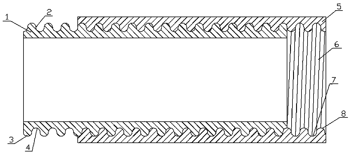
[0016] A preparation method of a copper-steel composite pipe, the structure of the copper-steel composite pipe is as follows figure 1 As shown, it consists of copper pipe 1 and steel pipe 5. Copper pipe thread teeth 2 are formed on the outer periphery of the copper pipe 1, and the copper pipe thread teeth 2 are composed of semicircular copper pipe thread tooth peaks 3 and semicircular copper pipe thread tooth valleys 4 with a radius of 0.2-0.5mm. The inner ring of the steel pipe 5 opens the steel pipe thread tooth 6, and the steel pipe thread tooth 6 is composed of a semicircular steel pipe thread peak 7 and a semicircular steel pipe thread valley 8 with a radius of 0.2-0.5mm. Degrease the surface of copper tube 1 and steel tube 5 with 10% NaOH solution. Rotate the copper pipe 1 and the steel pipe 5 with matching sizes in reverse, and use the copper pipe thread teeth 2 of the copper pipe 1 and the steel pipe thread teeth 6 of the steel pipe 5 to realize the reverse screwing o...

example 1

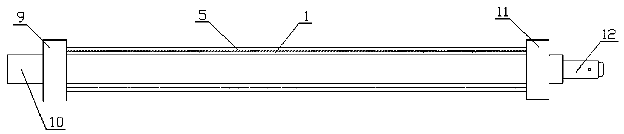
[0019] 20 steel with an outer diameter of 32 mm and a wall thickness of 4 mm and a pure copper tube with an outer diameter of 28.6 mm and a wall thickness of 1.0 mm are used as the outer tube and the copper tube as the inner tube. Both materials are annealed. Use a lathe to open the internal thread of the steel pipe. The shape of the crest and valley of the thread is a semicircle with a radius of 0.3mm. After cleaning with a 10% NaOH solution by mass fraction, dry it with cold air, and tighten the thread to form a composite pipe. ; Nitrogen gas is fed into the gas nozzle 10 of the composite pipe. When the pressure in the pipe reaches 2.3 MPa, the pressure relief valve opens the pressure relief mode, heats in the electromagnetic induction coil, stops heating, and cools the ferrule joint 9 and the inlet end with cooling water. Use a temperature measuring gun to measure the temperature of the ferrule joint 11 at the gas outlet, and keep the temperature at about 800°C. After heatin...

example 2

[0021] 20 steel with an outer diameter of 57 mm and a wall thickness of 4 mm and a pure copper tube with an outer diameter of 53.98 mm and a wall thickness of 1.5 mm are used as the outer tube and the copper tube as the inner tube. Both materials are annealed. Use a lathe to open the internal thread of the steel pipe. The shape of the crest and valley of the thread is a semicircle with a radius of 0.5mm. After cleaning with a 10% NaOH solution by mass fraction, dry it with cold air, and tighten the thread to form a composite pipe. ; Nitrogen gas is introduced into the gas nozzle 10 of the composite pipe. When the pressure in the pipe reaches 1.8 MPa, the pressure relief valve opens the pressure relief mode, heats in the electromagnetic induction coil, stops heating, and cools the ferrule joint 9 at the intake end with cooling water. For the ferrule joint 11 at the outlet end, use a temperature measuring gun to measure the temperature, keep the temperature at about 900 °C, stop ...


PUM

PropertyMeasurementUnit
radiusaaaaaaaaaa

Abstract

The invention relates to a copper and steel composite pipe and a preparation method thereof. The copper and steel composite pipe is composed of a copper pipe and a steel pipe. The steel pipe and the copper pipe are arranged in a sleeving manner. The copper pipe is provided with an external thread, the steel pipe is provided with an internal thread, wherein the external thread and the internal thread coordinate with each other. Alkali degreasing is carried out on the surface of the copper pipe and the surface of the steel pipe, and then, the copper pipe and the steel pipe are rotated and tightly coordinate with each other through the respective threads to form the composite pipe. One end of the composite pipe is provided with an air inlet end cutting sleeve connector and an air cock, the other end of the composite pipe is provided with an air outlet end cutting sleeve connector and an air release valve. Nitrogen is fed into the composite pipe from the air cock, the air release valve isopened to discharge air, internal pressure is kept in the pipe and is stable, warm keeping through heating is carried out, the composite pipe is cooled to the room temperature, finally, the head and the tail of the composite pipe are cut off, and the middle reserved part is the needed composite pipe. The copper and steel composite pipe and the preparation method thereof have the beneficial effectsthat the combination contact face of dissimilar metal is increased; and the nitrogen is fed into the copper pipe, the copper pipe can be prevented from being oxidized, dual functions of the temperature and the pressure are formed to accelerate diffusion, the diffusion time is shortened, and the combining strength is improved.

Description

technical field [0001] The invention relates to the application of composite materials, in particular to a copper-steel composite pipe and a preparation method thereof. Background technique [0002] Copper-steel composite pipe not only has the high strength and toughness of steel, but also has the excellent corrosion resistance of copper. It is used in the production of water supply, gas supply and oil pipelines and chemical industries. Compared with single-material copper pipes, copper-steel composite pipe materials are not only cheap, but also have better sealing performance and higher strength. At present, the manufacturing methods of copper-steel composite pipe include drawing composite method, casting composite method, spray deposition method, mechanical bonding method, and cold drawing and thermal diffusion method. Among them, the cold drawing and thermal diffusion method is relatively simple, but in the drawing process , the extension of the two metals is different, ...

Claims


Application Information

Patent Timeline
Patent Type & Authority Applications(China)
IPC IPC(8): B23P15/00F16L15/00F16L9/02
CPCB23P15/00F16L9/02F16L15/00
Inventor 白江虎李具仓任娟红陈立章马艳丽邵建勇王军宏孙爱楠宋宗亮
Owner 嘉峪关天源新材料有限责任公司
Why Eureka
Try Eureka