
Segmented laser light source system

A laser light source, segmented technology, used in optics, optical components, instruments, etc., can solve problems such as uneven speckle effect, achieve good engineering achievability, reduce overall size, and low cost.

Inactive Publication Date: 2018-03-13
SICHUAN CHANGHONG ELECTRIC CO LTD
View PDF6 Cites 3 Cited by
  • Summary
  • Abstract
  • Description
  • Claims
  • Application Information

AI Technical Summary

Problems solved by technology

[0005] The technical problem to be solved by the present invention is to provide a segmented laser light source system to solve the problems of speckle effect and inhomogeneity in laser projection display in the prior art

Method used


Image

  • Segmented laser light source system
  • Segmented laser light source system
  • Segmented laser light source system

Examples


Embodiment 1

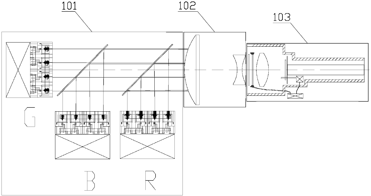
[0032] Such as figure 1 As shown, Embodiment 1 provides a segmented laser light source system, including a semiconductor laser light source 101, a telescopic beam reduction system 102, and a laser speckle extinction-homogenizer 103;

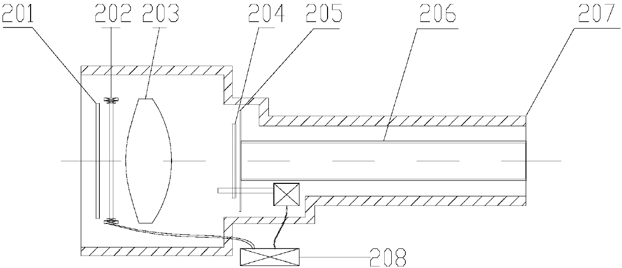
[0033] Such as figure 1 with figure 2 As shown, the semiconductor laser light source 101 includes an RGB diode array module, an array collimator lens, and a beam splitter. Dynamic diffusion wheel 204 , open-type shading plate 205 , homogenizing light guide rod 206 , mechanism housing 207 , and drive control board 208 .

[0034] The working principle of Embodiment 1 is: the RGB diode array modules output the laser light field in parallel through their corresponding array collimating lenses, and the laser light field is coupled into a laser light field with a common aperture through the beam splitter, and enters the telescopic beam reduction system 102 The telephoto beam reduction system 102 compresses the aperture of the laser light field, and...

Embodiment 2

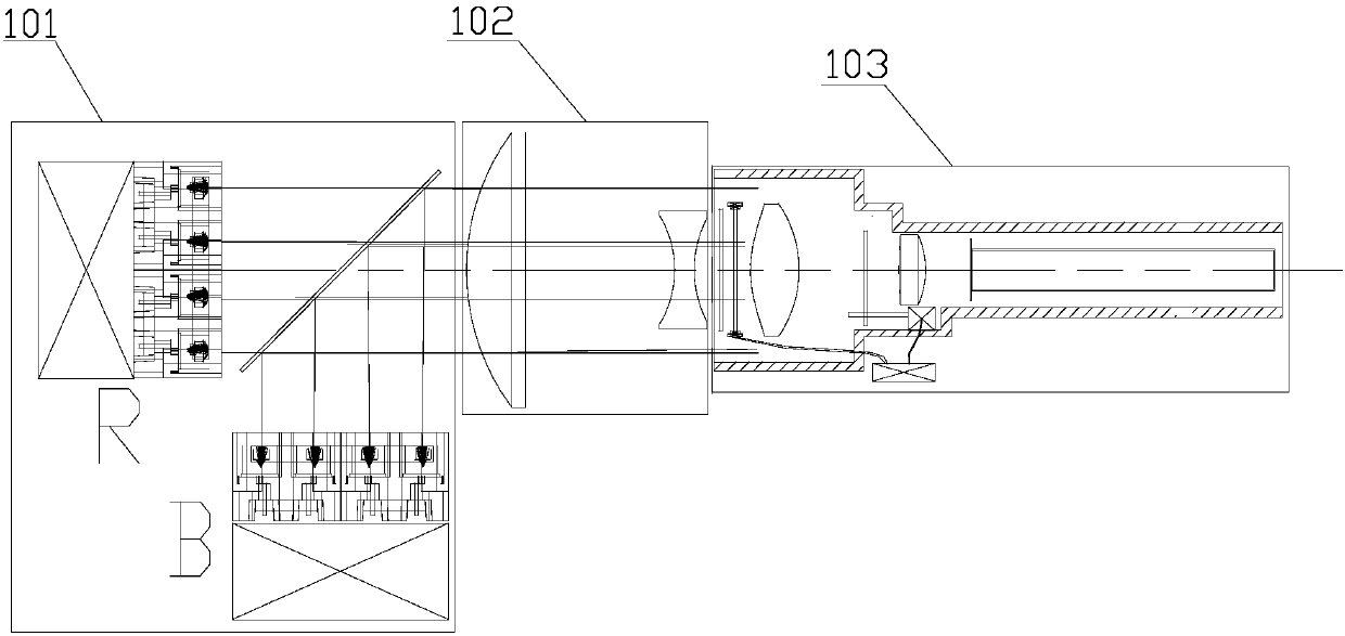
[0050] Such as image 3 As shown, Embodiment 2 provides a segmented laser light source system, including blue and red semiconductor laser light sources, a telescopic beam reduction system, and a laser speckle-dissipating homogenizer.

[0051] In this example, the blue and red semiconductor laser light sources include RB diode array module, array collimator lens, and beam splitter. The RB diode array module includes RB laser diode array, thermal copper plate, heat pipe, and heat sink; Arranged and installed on the respective heat-conducting copper plates. The heat-conducting copper plates are inserted with heat-conducting tubes. The heat-conducting tubes contain refrigerant. The arrangement and layout are consistent with the laser diode array, forming a one-to-one correspondence.

[0052] Similar to Example 1, the laser speckle dissipation-homogenizer in Example 2 includes a static diffuser 201, a phase adjuster 202, a condenser lens 203, an integrated fluorescence-filter whee...


PUM


Abstract

The invention relates to the technical field of laser display, discloses a segmented laser light source system, and solves problems of speckle effect and non-uniformity of laser projection display inthe prior art. The system comprises a semiconductor laser light source, a telescoping beam compression system, and a laser speckle elimination-homogenizer, the semiconductor laser light source comprises a diode array module, array collimating lenses and a beam splitter, the diode array module outputs laser light fields in parallel through respective corresponding array collimating lenses, the laser light fields are coupled to a common-aperture laser light field through the beam splitter and enter the telescoping beam compression system, the telescoping beam compression system performs aperturecompression on the laser light field, the compressed laser light field is output to the laser speckle elimination-homogenizer, the laser speckle elimination-homogenizer performs homogenization and speckle elimination processing on the compressed light field, and a uniform square light field is generated at a light stick outlet thereof. The system is applicable to projection systems including projectors.

Description

technical field [0001] The invention relates to the technical field of laser display, in particular to a segmented laser light source system. Background technique [0002] At present, the lighting part of the projection system mostly uses LED light sources. Due to the low electro-optic efficiency, it does not meet the energy-saving and high-brightness projection requirements. With the maturity of semiconductor laser diode technology, laser light sources are used as a new type of light source with high brightness and high collimation. It has the characteristics of wide color gamut, high brightness, high saturation, low energy consumption, long life, etc., and is being gradually applied to projection, lighting and other fields. [0003] In the actual application of the laser light source, due to the high coherence of the laser, when the laser is reflected or transmitted through the rough surface, the optical path difference is caused by the difference in height fluctuation bas...

Claims


Application Information

Patent Timeline
Patent Type & Authority Applications(China)
IPC IPC(8): G02B27/09G02B27/48G03B21/20
CPCG02B27/0922G02B27/0961G02B27/48G03B21/2033
Inventor 张金旺何龙田海军陈志洁
Owner SICHUAN CHANGHONG ELECTRIC CO LTD
Learn More