
Shield knife disc hydraulic driving system and method in intelligent variable power control mode

A control mode and shield cutter head technology, which is applied in earthwork drilling, mining equipment, tunnels, etc., can solve the problems of power waste, large fluctuation range of cutter head speed, and inability to adjust input power, so as to improve system control accuracy, Simplified system structure and strong adaptability

Active Publication Date: 2018-03-27
NORTH CHINA UNIV OF WATER RESOURCES & ELECTRIC POWER
View PDF4 Cites 8 Cited by
  • Summary
  • Abstract
  • Description
  • Claims
  • Application Information

AI Technical Summary

Problems solved by technology

The constant power control system can control the output torque and speed of the cutter head in real time to adapt to the changing load conditions, and has a strong adaptability to complex geological formations. Adjustment, which will cause a large waste of power in the actual construction site, especially in the working conditions with variable geological conditions
And when the load changes greatly, the cutterhead speed fluctuates in a large range, which is not conducive to the normal operation of the shield machine

Method used


Image

  • Shield knife disc hydraulic driving system and method in intelligent variable power control mode
  • Shield knife disc hydraulic driving system and method in intelligent variable power control mode
  • Shield knife disc hydraulic driving system and method in intelligent variable power control mode

Examples


experiment example

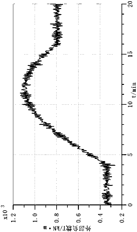
[0044] Taking a certain type of shield machine as an example, working in two geological layers of sandy soil and soft soil, its working load curve is as follows: image 3 shown.

[0045] Under this load condition, the cutter head hydraulic drive system of the present invention is set to a 3-level power working mode, and the joint simulation is carried out with the help of AMESIM and SIMULINK software. The simulation schematic diagram is as follows Figure 4 , Figure 5 shown.

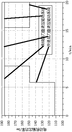
[0046] Through the combined simulation analysis, compared with the traditional constant power cutter head hydraulic drive system, the cutter head hydraulic drive system of the present invention can automatically select the corresponding power working mode according to the load size and the cutter head speed, such as Image 6 shown.

[0047] The cutter head hydraulic drive system of the present invention and the traditional constant power cutter head hydraulic drive system compare the cutter head spee...


PUM


Abstract

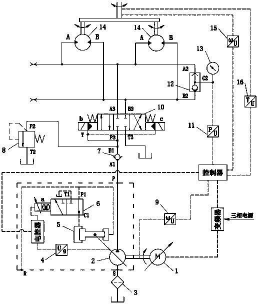
Disclosed are a shield knife disc hydraulic driving system and method in an intelligent variable power control mode. The shield knife disc hydraulic driving system includes a motor, a variable pump and a one-way valve connected with one another in sequence. The one-way valve is connected with an overflow valve and a three-position four-way electro-hydraulic directional valve. The three-position four-way electro-hydraulic directional valve is connected with a constant displacement motor and a shuttle valve. The motor is a three-phase asynchronous motor. An input shaft and an output shaft of themotor are provided with a frequency converter and a first revolution speed transducer. An angular transducer in a swash plate of the variable pump is connected with a variable pump electric controller. A left cavity of a servo plunger piston of the variable pump communicates with a control oil port C1 of a two-position three-way high-speed switch valve. a right cavity of the servo plunger pistoncommunicates with an external pilot pressure oil port R. an oil inlet P1 and an oil returning mouth T1 of the two-position three-way high-speed switch valve communicates with the external pilot pressure oil port R and an oil box correspondingly. A second revolution speed transducer, a torque transducer, a frequency changer on the shield knife disc, an electric controller of the variable pump, a second revolution speed transducer and a pressure sensor of a shuttle valve oil outlet C2 pipe are all connected with a controlling device.

Description

technical field [0001] The invention relates to a hydraulic control circuit, in particular to a shield cutter head hydraulic drive system adopting an intelligent variable power control mode. Background technique [0002] The shield machine is a combination of multi-disciplinary and multi-field technologies. With its advantages of high efficiency, speed, high quality and safety, it has become the most widely used large-scale tunneling engineering equipment in various countries in the world. As the core component of the shield machine, the cutter head hydraulic drive system provides power for the cutter head to cut the front soil, and is the main working device for tunneling work. It has the characteristics of large volume and high power. [0003] During the actual construction process, the shield machine often passes through different types of strata, and the engineering characteristics of different strata are also different. When the shield machine is excavating, the torque...

Claims


Application Information

Patent Timeline
Patent Type & Authority Applications(China)
IPC IPC(8): E21D9/093E21D9/08
CPCE21D9/08E21D9/093
Inventor 郝用兴郑淑娟周建军范素香雷超周洋刘玉洋郝亦龙
Owner NORTH CHINA UNIV OF WATER RESOURCES & ELECTRIC POWER
Learn More