
Resonant cavity inside-pumped disk laser

A pump laser and resonant cavity technology, applied in the field of optoelectronics, can solve the problems of high cost, increased cost, and complex system of conjugated double paraboloids, and achieve the effects of increasing industrial cost, improving uniformity, and overcoming the reduction of absorption coefficient

Pending Publication Date: 2018-03-27
HUAZHONG UNIV OF SCI & TECH
View PDF5 Cites 4 Cited by
  • Summary
  • Abstract
  • Description
  • Claims
  • Application Information

AI Technical Summary

Problems solved by technology

First, the conjugate double paraboloid is expensive and requires two expensive parabolic mirrors (imported parabolic mirrors with good surface shape, generally with low pv value and small focusing imaging aberration, about 40,000 US dollars per piece) , the system is complex; and our solution only needs common spherical mirrors (one piece is less than 100 RMB)
Second, the pumping scheme of the conjugate double paraboloid system with multiple pumps is to increase the pumping times by spatially shifting the pumping light. The disadvantage of this method is that with the increase of the pumping times, the paraboloid The caliber (size) of the mirror will also increase accordingly, and the cost will also increase; and in our scheme, the number of pumps is more than that of the double paraboloid multiple pumps (theoretically infinitely many times), and there is no need to make any changes to the size of the

Method used


Image

  • Resonant cavity inside-pumped disk laser
  • Resonant cavity inside-pumped disk laser
  • Resonant cavity inside-pumped disk laser

Examples


Embodiment 1

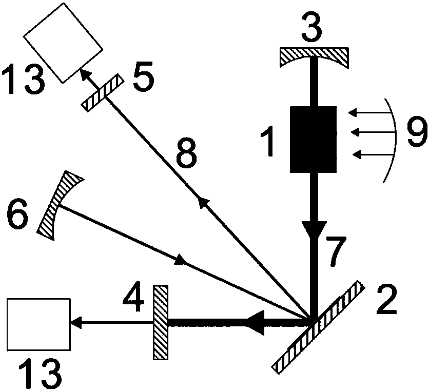
[0054] The resonant cavity of the primary laser in Embodiment 1 is a linear cavity, which is the simplest case.

[0055] The gain material 1 of the first-level laser is Nd:YAG, 9 is the pump source of Nd:YAG, 7 is the laser oscillating in the cavity of the first-level laser, the center wavelength is 1064nm, the spherical cavity mirror is 3 pairs of 1064nm high reflection, and the pair of 2um High antireflection. Here, the dichroic mirror is used to prevent the 2um laser generated by the disc 2 from forming parasitic oscillation between the resonant cavities 3-2. Disc 2 is Tm:YAG, cavity mirror 6 is a 2um full reflection mirror, output mirror 5 is a 2um partial reflection mirror, the function of output mirror 5 is to output 2um laser from the system, and 13 is a power meter, which is used to monitor the primary laser cavity The size of the power within.

[0056] In the experiment, we adjusted the angle of the reflector 3 to make the laser 7 resonate between the resonator 2 an...

Embodiment 2

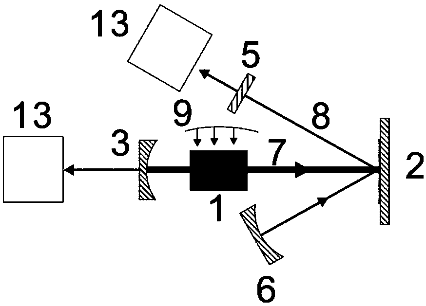
[0058] When the absorption coefficient of the disk 2 in the embodiment 1 is so low that the pump light absorbed by the disk 2 is not enough to generate laser light, the V-type pumping method in the embodiment 2 can simply solve this situation.

[0059] The gain material 1 of the first-level laser is Nd:YAG, 9 is the pump source of Nd:YAG, 7 is the laser oscillating in the cavity of the first-level laser, the center wavelength is 1064nm, the spherical cavity mirror is 3 pairs of 1064nm high reflection, and the pair of 2um High antireflection. The dichroic mirror is used here to prevent the 2um laser generated by the disc 2 from forming parasitic oscillation between the resonant cavities 3-4. Plane mirror 4 is a 1064nm full mirror disc. 2 is Tm: YAG, the cavity mirror 6 is a 2um full reflection mirror, the output mirror 5 is a 2um partial reflection mirror, the function of the output mirror 5 is that the system outputs 2um laser, and 13 is a power meter, which is used to monito...

Embodiment 3

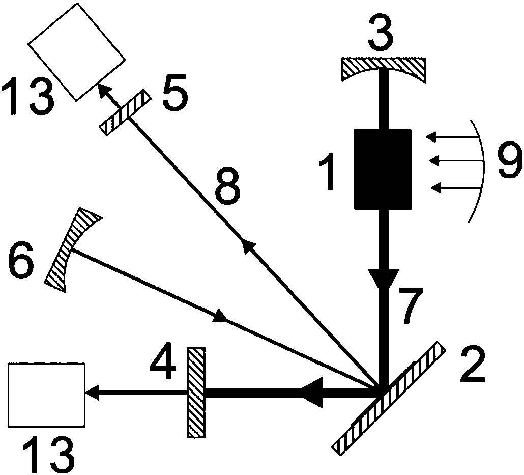
[0063] When the pumping power density of the first-stage laser in embodiment 1 and embodiment 2 is too low, so that the absorption coefficient of the disc 2 is too low to generate laser light, multiple first-stage lasers in embodiment 3 are connected in series The intracavity pumping scheme can solve this situation.

[0064] The gain material 1 of the primary laser is Nd:YAG, 9 is the pump source of Nd:YAG, and 7 is the laser oscillating in the cavity of the primary laser, and the center wavelength is 1064nm. Here we use two primary lasers connected in series as the pump source.

[0065] The spherical cavity mirror has 3 pairs of 1064nm high reflection and 2um high anti-reflection. Here, the dichroic mirror is used to prevent the 2um laser generated by the disc 2 from forming parasitic oscillation between the resonant cavities 3-3. 2 is Tm: YAG, the cavity mirror 6 is a 2um full reflection mirror, the output mirror 5 is a 2um partial reflection mirror, the function of the ou...


PUM


Abstract

The invention discloses a resonant cavity inside-pumped disk laser, which comprises an active gain mirror, a pump laser with the active gain mirror inserted in a resonant cavity, and a disk laser resonant cavity. According to the invention, a resonant cavity is based on a conventional pump cavity and is further inserted with a gain material made into a sheet to form a reflective mirror of the resonant cavity, or is a resonant cavity formed by amplifying the stimulated radiation light of the sheet crystal itself. According to the invention, the high-power roundtrip laser in a laser resonant cavity is used to achieve the multi-pumping purpose for the disk laser, the disk laser crystal pumped power density in the resonant cavity is more than ten times higher than that outside the cavity, andthe absorption efficiency of the pump light by the disk crystal can be improved, especially for non-absorption peak pumping conditions. In the invention, the pump resonant cavity and the disk laser resonant cavity are independent of each other, the cascade pumping of the disk laser can be realized, and the Q modulation of the pump cavity can also realized to obtain the multi-wavelength, the narrowpulse width and the high peak power pulsed laser output.

Description

technical field [0001] The invention belongs to the technical field of optoelectronics, and more specifically relates to a novel disk solid-state laser. Background technique [0002] Because of its thin gain medium, the heat conduction direction is consistent with the laser light output direction, the thermal lens effect is weak, the heat transfer effect is good, and it can withstand large laser power density, and can obtain pulsed laser output from continuous to high peak power. recognized by academia and industry. [0003] However, because the disk laser crystal is very thin, the thickness is generally 50 microns to 500 microns, and the single absorption of pump light is weak, so it is necessary to construct a complex structure to pump the disk crystal multiple times, such as Trumpf The company's parabolic mirror and right-angle steering prism multiple pumping scheme, Huazhong University of Science and Technology's double paraboloid conjugate imaging multiple pumping sche...

Claims


Application Information

Patent Timeline
Patent Type & Authority Applications(China)
IPC IPC(8): H01S3/094H01S3/06
CPCH01S3/0604H01S3/094084
Inventor 朱晓陈永骞朱广志王海林
Owner HUAZHONG UNIV OF SCI & TECH
Learn More