Low-water heating/cooling device for internal-combustion engine

A cooling device, low water temperature technology, used in engine cooling, internal combustion piston engines, liquid cooling, etc., can solve problems such as corrosion of metal parts

Inactive Publication Date: 2018-03-27
DENSO CORP
View PDF8 Cites 7 Cited by
  • Summary
  • Abstract
  • Description
  • Claims
  • Application Information

AI Technical Summary

Problems solved by technology

However, if there is a lot of moisture in the EGR gas returning to the intake passage, when the intake gas mixed with the EGR gas and the intake air (fresh air) is cooled by the intercooler, condensed water will be generated, and there will be water due to the condensed water. Possibility of corrosion of metal parts, etc.

Method used


Image

  • Low-water heating/cooling device for internal-combustion engine
  • Low-water heating/cooling device for internal-combustion engine
  • Low-water heating/cooling device for internal-combustion engine

Examples


Embodiment 1

[0028] based on Figure 1 to Figure 6 Example 1 of the present disclosure will be described.

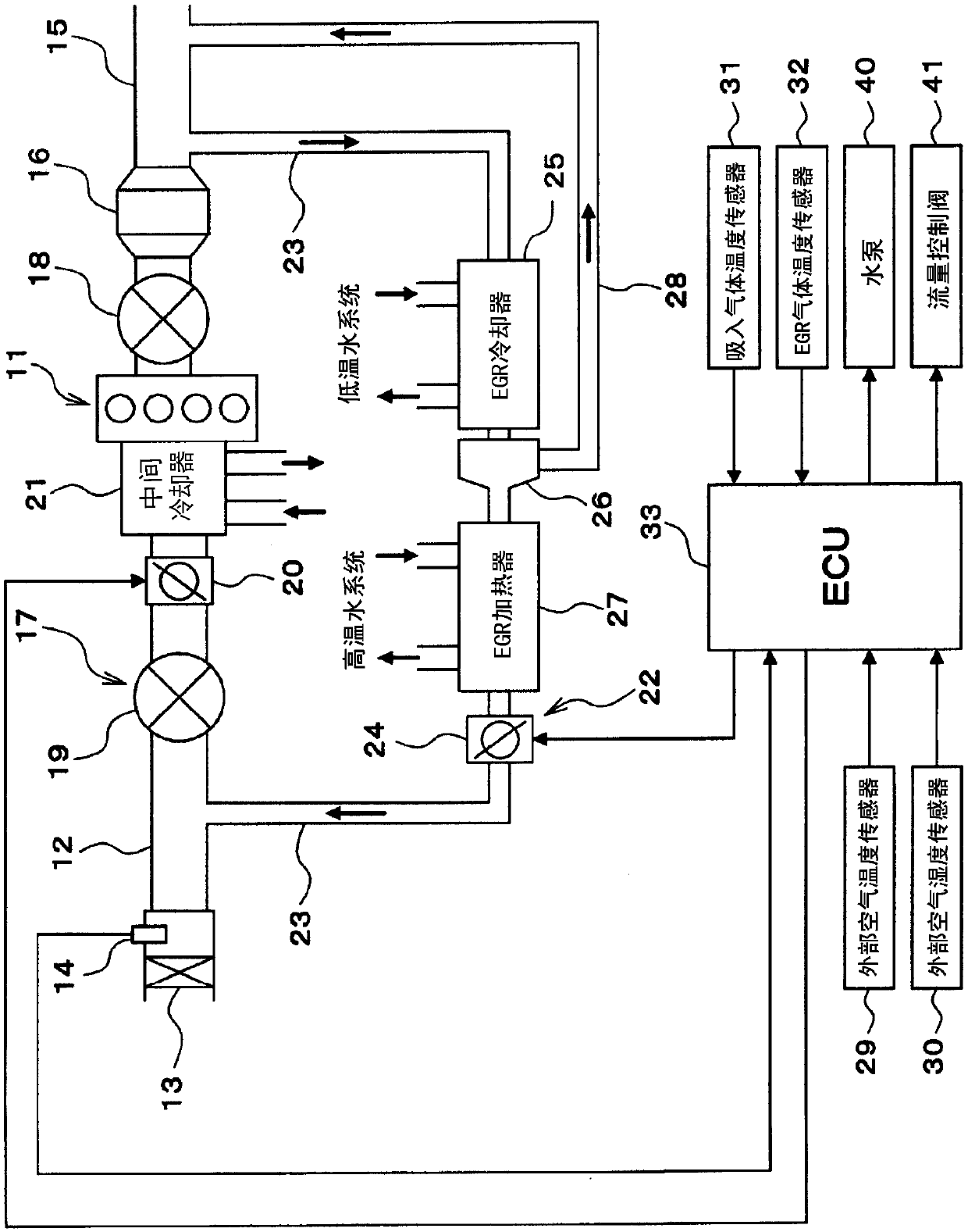
[0029] First, based on figure 1 The schematic configuration of the engine control system will be described.

[0030] An air cleaner 13 is provided at the most upstream portion of an intake pipe 12 (intake passage) of an engine 11 which is an internal combustion engine. On the downstream side of the air cleaner 13, an air flow meter 14 for detecting the amount of intake air is provided. On the other hand, the exhaust pipe 15 of the engine 11 is provided with a countermeasure against CO, HC, and NO in the exhaust gas. X etc. Catalysts 16 such as three-way catalysts for purification.

[0031] An exhaust turbine-driven supercharger 17 for supercharging intake gas is attached to the engine 11 . Here, the intake gas may be only intake air (fresh air), but may be a mixed gas of intake air and EGR gas. In the supercharger 17 , an exhaust turbine 18 is arranged on the upstream side of ...

Embodiment 2

[0092] Next, use Figure 7 as well as Figure 8 Example 2 of the present disclosure will be described. Here, descriptions of parts that are actually the same as those in Embodiment 1 are omitted or simplified, and parts that are different from Embodiment 1 are mainly described.

[0093] In this embodiment 2, use ECU33 to execute Figure 7 According to the flow control program, the flow control valve 41 is controlled according to the external air environment and the operating state of the engine, so that the flow ratio between the intercooler 21 and the EGR cooler 25 is changed.

[0094] exist Figure 7 In the flow rate control routine of , firstly, in 301 , the engine operating state, outside air temperature, and outside air humidity are obtained, and then proceeds to 302 , where it is determined whether the engine 11 is in stable operation.

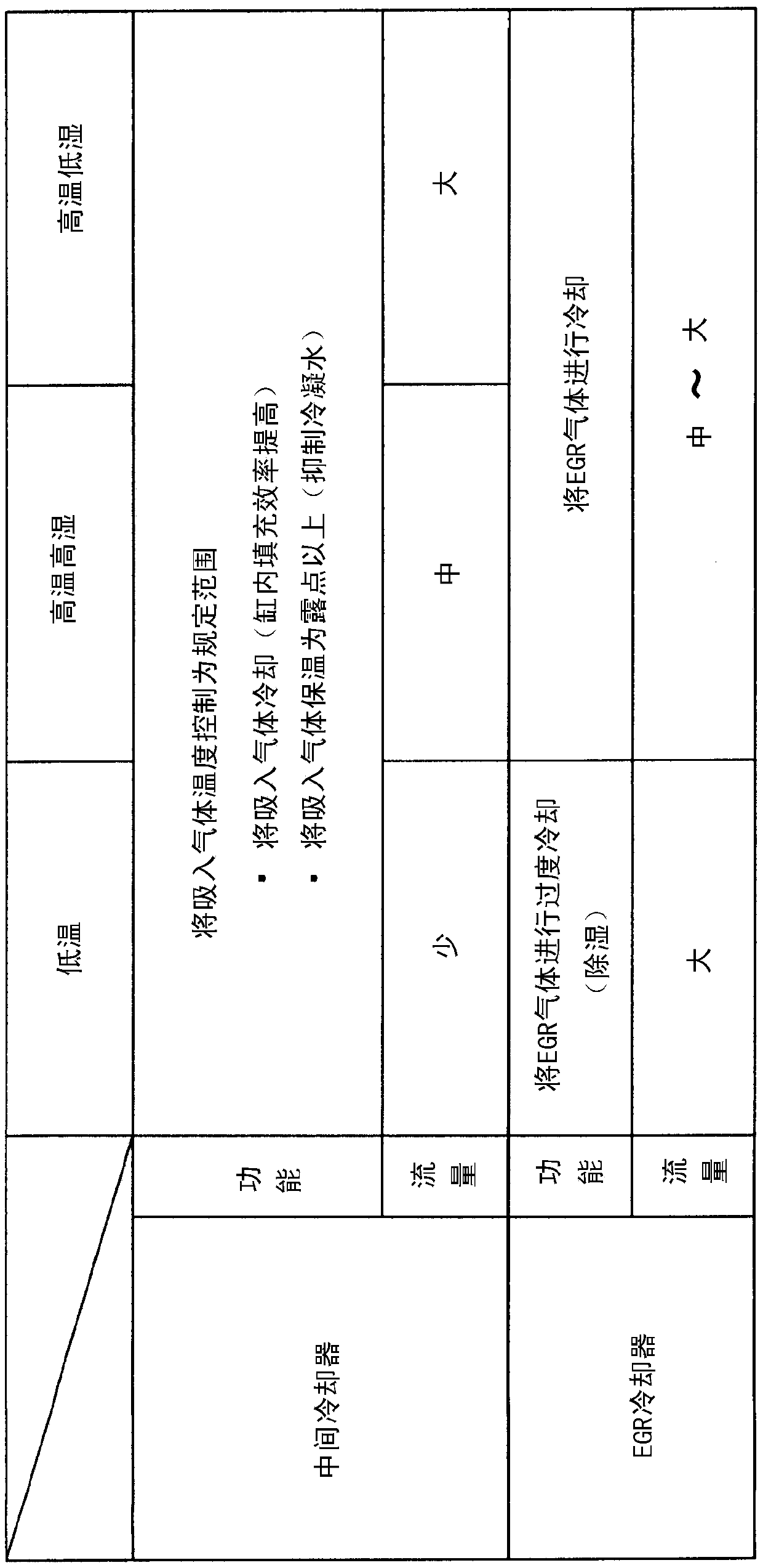
[0095] In 302, if it is determined that the steady operation is in progress, proceed to 303, refer to Figure 8 The shown correspo...

Embodiment 3

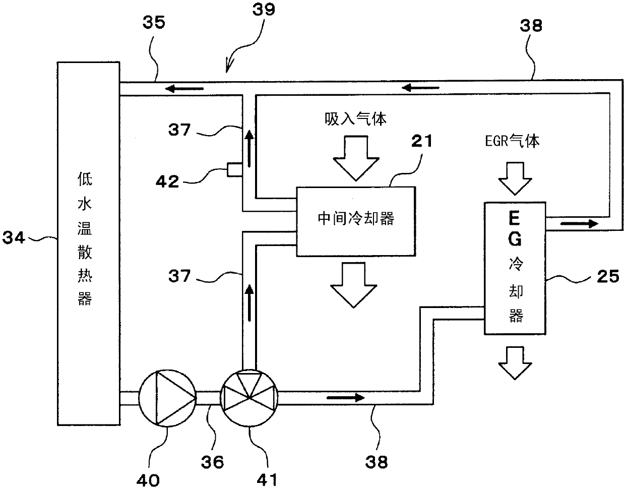
[0102] Next, use Figure 9 as well as Figure 10 Example 3 of the present disclosure will be described. Among them, the same symbols are attached to the parts that are actually the same as those in Embodiment 1, and descriptions are omitted or simplified, and the parts that are different from Embodiment 1 will be mainly described.

[0103] In this embodiment 3, if Figure 9 As shown, the flow rate ratio of the intercooler 21 to the EGR cooler 25 is adjusted by providing a flow control valve 41 in the intercooler flow path 37 and adjusting the flow rate of the intercooler 21 by the flow control valve 41 . Alternatively, it can also be used as Figure 10 As shown, the flow rate ratio of the intercooler 21 to the EGR cooler 25 is adjusted by providing a flow control valve 41 in the EGR cooler flow path 38 and adjusting the flow rate of the EGR cooler 25 using the flow control valve 41 . In both cases, the flow rate ratio between the intercooler 21 and the EGR cooler 25 can be...


PUM


Abstract

Provided is a low-water heating / cooling device for an internal-combustion engine, said low-water heating / cooling device being equipped with: an EGR device (22) that recirculates some of an exhaust gasof an internal-combustion engine (11) back to an intake passage (12) as an EGR gas; and a low-water heating / cooling water circuit (39) that circulates a cooling water to an intercooler (21), which cools an intake gas of the internal-combustion engine, and an EGR cooler (25), which cools the EGR gas. The low-water heating / cooling device is further equipped with: a flow-rate control valve (41) thatregulates the flow-rate ratio of the cooling water flowing into the intercooler and the cooling water flowing into the EGR cooler; and control units (33, 101-120, 201-205) that change the flow-rate ratio of the cooling water flowing into the intercool and the cooling water flowing into the EGR cooler by controlling the flow-rate control valve in accordance with the outside air environment and theoperation state of the internal-combustion engine.

Description

[0001] Cross-references to related applications [0002] The present invention is based on Japanese Patent Application No. 2015-94785 filed on May 7, 2015, the entire contents of which are incorporated herein. technical field [0003] The present disclosure relates to a low-water-temperature cooling device for an internal combustion engine including a low-water-temperature cooling water circuit for circulating cooling water to an intercooler and an EGR cooler. Background technique [0004] An internal combustion engine installed in a vehicle is equipped with an EGR device that returns a part of the exhaust gas to the intake passage as EGR gas for the purpose of improving fuel consumption performance, reducing knocking, and exhaust emissions. However, if there is a lot of moisture in the EGR gas flowing back into the intake passage, condensed water will be generated when the intake gas mixed with the EGR gas and intake air (fresh air) is cooled by the intercooler. Possibilit...

Claims


Application Information

Patent Timeline
Patent Type & Authority Applications(China)
IPC IPC(8): F02M26/06F01P7/16F02M26/33
CPCF01P7/16F02M26/06F02B29/0418F02B29/0443F02B29/0493F02M26/33F02M26/28F02M26/35Y02T10/12F01P3/18F01P2007/146
Inventor 南敬太郎宫川雅志市原英明
Owner DENSO CORP
Why Eureka
Try Eureka