A dynamic photoelastic ultrasound imaging method and system

An ultrasonic imaging system and dynamic photoelastic technology, applied in the field of ultrasonics, can solve problems such as low extinction ratio, large edge energy jitter, and inability to observe ultrasonic signals, so as to improve signal-to-noise ratio, good ultrasonic imaging effect, and improve system sensitivity Effect

Inactive Publication Date: 2020-04-14
INST OF ACOUSTICS CHINESE ACAD OF SCI
View PDF5 Cites 0 Cited by
  • Summary
  • Abstract
  • Description
  • Claims
  • Application Information

AI Technical Summary

Problems solved by technology

After the laser beam is directly expanded, it still has the original spatial distribution, so the sample cannot be uniformly exposed, which affects the imaging quality and quantitative measurement accuracy of the ultrasound.
[0004] Existing laser-based dynamic photoelastic ultrasonic imaging systems generally use fundamental transverse mode lasers with Gaussian distribution, which do not shape the spatial distribution of beam energy, so the sample cannot be uniformly exposed, resulting in brighter central parts of the image, resulting in measurement errors
In addition, the pixels in the center of the image are prone to saturation, which is not conducive to quantitative measurement
If the Gaussian beam is shaped by a flat-hat light shaper, a more uniform beam can be obtained, but the edge energy jitter is large, which is not conducive to imaging and quantitative measurement, and the cost is very high
[0005] In addition, the polarizers and analyzers of existing commercial or self-developed photoelastic systems generally use resin polarizers, which have a low extinction ratio (not exceeding 1000:1), resulting in large noise in the received optical signal exist, and are difficult to remove by image processing methods, so the signal-to-noise ratio and sensitivity of the system are low, and weak ultrasonic signals cannot be observed

Method used


Image

  • A dynamic photoelastic ultrasound imaging method and system
  • A dynamic photoelastic ultrasound imaging method and system
  • A dynamic photoelastic ultrasound imaging method and system

Examples


Embodiment 1

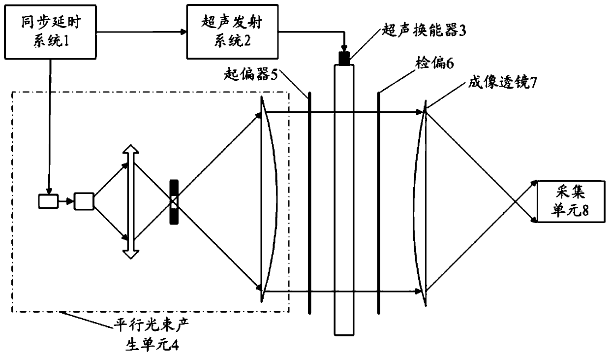
[0072] Examples verify the homogenization and imaging effects of the present invention. In this example, in order to obtain a larger field of view and better explain the problem, the polarizer and analyzer still use traditional resin polarizers. The light source used in the system is a nanosecond-level pulsed laser, which emits green light, and the spatial mode is multi-mode, which is manifested as multiple bright spots. Please refer to figure 1 , the synchronous delay system first sends a trigger signal to the ultrasonic transmitting system, and the ultrasonic transmitting system sends out an electric pulse signal (voltage 1000V) to excite the ultrasonic transducer to generate ultrasound, which propagates in the glass (here the sample is not limited to glass, and can also be other transparent solid). After the ultrasound propagates for a period of time, the synchronous delay system sends a trigger signal to the laser, and the laser emits pulsed laser light, which passes thro...

Embodiment 2

[0075] This embodiment verifies the high sensitivity and the ability to observe weak sound fields of the present invention. The resin polarizer in the system of Example 1 was replaced with a Glan-Taylor prism, and then the voltage of the ultrasonic excitation signal was lowered from 1000V to 10V, at which point the ultrasonic energy became extremely weak. Such as Figure 7 As shown, it is the image collected by using the original resin polarizer. There are only noise spots in the picture, and the ultrasonic signal cannot be distinguished. Figure 8 Shown is the image collected by adopting the solution of the present invention, and ultrasonic fringes can be clearly distinguished. It should be noted that due to the limitation of the clear aperture of the Glan Taylor prism, Figure 8 The streaks captured are only Figure 6 part of the field of view.

[0076] Therefore, it can be seen that the present invention can significantly improve the system sensitivity, realize better u...


PUM


Abstract

The invention relates to a dynamic photoelastic ultrasonic imaging method and system. The system comprises a synchronous time-delay system, an ultrasonic emission system, an ultrasonic energy transducer, a parallel light beam generation unit, a polarizer, a sample placing point, a polarization analyzer, an imaging lens and a collection unit, wherein the sample placing point is positioned between the polarizer and the polarization analyzer and used to place an observation sample; the parallel light beam generation unit generates parallel light beams in uniform light-intensity distribution; thepolarizer and the polarization analyzer process the parallel light beams to obtain a light pulse signal of high signal to noise ratio; the imaging lens carries out imaging on the received light pulsesignal; and the collection unit realizes ultrasonic imaging by collecting light pulse signals passing the imaging lens for multiple times and overlapping the signals. Thus, the system sensitivity canbe improved substantially, a better ultrasonic imaging effect is realized, and a weak ultrasonic field in a solid body is observed.

Description

technical field [0001] The present application relates to the field of ultrasonic technology, in particular to imaging and systems of ultrasonic sound fields in solids, and in particular to a dynamic photoelastic ultrasonic imaging method and system. Background technique [0002] Quantitative measurement of ultrasonic sound field in solids is of great significance for studying the propagation and scattering of ultrasonic waves in solids and developing new technologies for ultrasonic nondestructive testing. [0003] In "Scattering of Ultrasound in Solids" published by National Defense Industry Press in 1994, a dynamic laser photoelastic ultrasonic imaging device was disclosed, and a method for measuring the ultrasonic sound field in transparent solids was discussed. The light source of the system is a pulsed laser, which has the advantages of high energy and short pulse compared with LED light source. The laser beam emitted by the pulsed laser has a single-mode or multi-mode...

Claims


Application Information

Patent Timeline
Patent Type & Authority Patents(China)
IPC IPC(8): G01H9/00
CPCG01H9/002
Inventor 安志武胡中韬廉国选王小民毛捷冷涛宋波陈秋颖闫冉温孟阁
Owner INST OF ACOUSTICS CHINESE ACAD OF SCI
Why Eureka
Try Eureka