Lithium-ferrous disulfide battery and assembly method thereof

A ferrous disulfide and assembly method technology, applied in the internal connection of lithium-ferrous disulfide battery, lithium-ferrous disulfide battery and its assembly field, can solve the complicated resistance welding process, battery safety hazards, and poor resistance welding problems such as high rate, to achieve the effect of realizing automated mass production, reducing production costs, and avoiding high defect rate

Active Publication Date: 2018-04-06
EVE ENERGY CO LTD
View PDF3 Cites 3 Cited by
  • Summary
  • Abstract
  • Description
  • Claims
  • Application Information

AI Technical Summary

Problems solved by technology

However, there are deficiencies in the method of resistance welding: (1) The resistance welding process is complicated and the operation cost is high
In addition, the stability of the resistance welding equipment, the size of the current, etc. will affect the welding effect
(2) Due to too many factors affecting resistance welding, the defect rate of resistance welding is very high, mainly due to problems such as virtual welding, welding penetration, welding deviation and welding explosion.
(3) During the welding process, the molten metal shavings at the welding place will splash around, and the splashed metal shavings may burn through the diaphragm and cause an internal short circuit of the battery
Even if the metal debris produced by welding does not burn the diaphragm, it will cause great hidden danger to the safety of the battery if it remains in the battery cell
(4) There will be a protruding solder joint at the welding point of resistance welding. Since the anti-rust coating at the solder joint is damaged, there is a risk of rust if the battery is in a humid environment
(5) Resistance welding still lacks reliable non-destructive testing methods at present, and the welding quality can only be checked by destructive tests of process samples and workpieces, as well as various monitoring techniques to ensure

Method used


Image

  • Lithium-ferrous disulfide battery and assembly method thereof
  • Lithium-ferrous disulfide battery and assembly method thereof
  • Lithium-ferrous disulfide battery and assembly method thereof

Examples


Embodiment 1

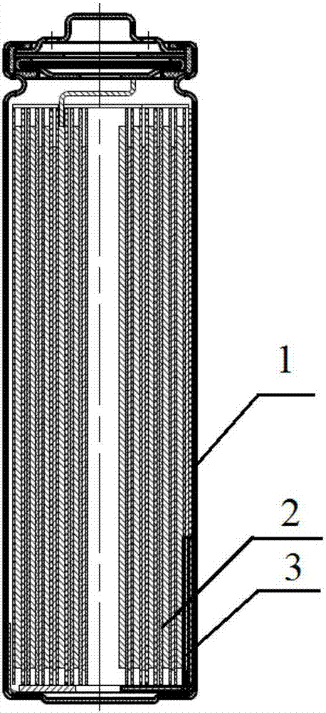
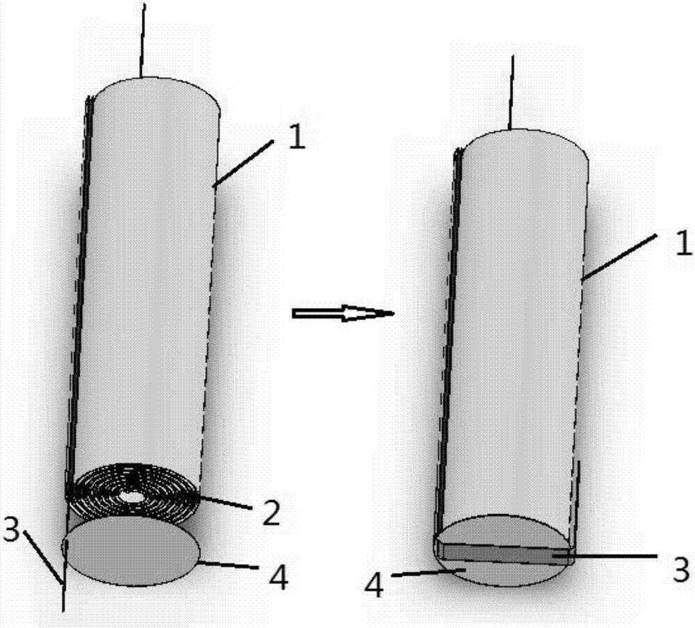
[0027] A lithium-ferrous disulfide battery includes a wound cell 2 and a casing 1. The negative electrode tab 3 exposed outside the wound cell 2 is in contact with the side wall of the casing 1. Among them, the negative pole lug 3 is a stainless steel strip, which is 10 mm longer than the diameter of the wound cell 2, and the outer shell is a nickel-plated steel shell.

[0028] The assembly steps are as follows:

[0029] Pass the negative electrode tab 3 of the wound cell 2 through the square hole of the 0.1mm thick PP insulation gasket 4 and bend it at 90°. The diameter of the insulation gasket 4 is the same as the diameter of the wound cell 2. The square hole The size is the same as the size of the negative electrode tab 3; then the extra tab at the bottom of the battery core is bent 90° against the battery core, and finally the battery core is placed in the case 1, which completes the negative tab tab 3 and the case 1 connection.

[0030] According to conventional methods and ot...

Embodiment 2

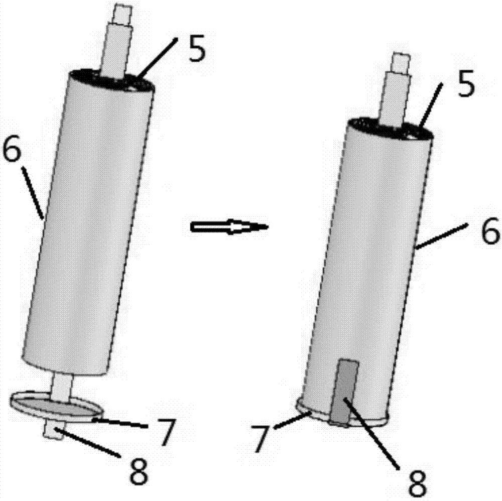
[0032] A lithium-ferrous disulfide battery includes a wound cell 5 and a casing 6. The negative electrode tab 8 exposed outside the wound cell 5 is in contact with the side wall of the casing 6. Among them, the negative pole lug 8 is a copper strip, which is 15 mm longer than the diameter of the wound cell 5, and the outer shell 6 is a nickel-plated steel shell.

[0033] The assembly steps are as follows:

[0034] Pass the negative electrode tab 8 of the wound cell 5 through the square hole of the 0.5mm thick PET insulation cover 7 and bend it at 90°. The diameter of the insulation cover 7 is the same as the diameter of the wound cell 5. The square hole The size of the battery is the same as the size of the negative electrode tab 8; then the extra tab at the bottom of the battery cell is bent 90° against the battery core, and finally the battery core is placed in the case 6, which completes the negative tab tab 8 and the case 6's connection.

[0035] According to conventional metho...

Embodiment 3

[0037] A lithium-ferrous disulfide battery includes a wound electric core and a casing, and the negative electrode tab exposed outside the wound electric core is in contact with the side wall of the casing. Among them, the negative pole lug is a nickel-plated steel strip, which is 13mm longer than the diameter of the wound cell, and the outer shell is a nickel-plated steel shell.

[0038] The assembly steps are as follows:

[0039] Pass the negative electrode tab of the wound cell through the square hole of the 0.3mm thick PVC insulating sleeve and bend it at 90°. The diameter of the insulation sleeve is the same as the diameter of the wound cell, and the size of the square hole is the same as that of the negative electrode. The size of the lugs is the same; then the extra lugs at the bottom of the cell are bent 90° against the cell, and finally the cell is placed in the shell to complete the connection between the negative pole and the shell.

[0040] According to conventional meth...


PUM

PropertyMeasurementUnit
diameteraaaaaaaaaa
thicknessaaaaaaaaaa

Abstract

The invention relates to a lithium-ferrous disulfide battery and an assembly method thereof. The battery comprises a winding battery cell and a shell, wherein a negative tab exposed out of the windingbattery cell is in contact connection with a side wall of the shell. The assembly method comprises the steps of firstly, allowing the negative tab of the winding battery cell to penetrate through a square hole of an insulation cushion piece, and bending the negative tab by 90 degrees; secondly, bending the tab exceeding the bottom of the battery cell by 90 degrees again to be in contact with thebattery cell; and finally, sleeving the battery cell in the shell to complete connection of the negative tab and the shell. A welding mode of the prior art is substituted by a contact mode, the defects of high unfavorable rate, potential risk, complicated process, poor controllability and the like of the welding mode are prevented, and the fabrication cost is reduced; and a test result shows thatthe lithium-ferrous disulfide battery has favorable performance.

Description

Technical field [0001] The invention relates to the technical field of lithium primary batteries, in particular to a method for internal connection of a lithium-ferrous disulfide battery, in particular to a lithium-ferrous disulfide battery and an assembly method thereof. Background technique [0002] Lithium-ferrous disulfide (Li / FeS 2 ) The battery is a low-voltage lithium primary battery, and its working voltage platform is 1.5V, so it is the same size as the alkaline manganese (Zn / MnO 2 ) Batteries, nickel-hydrogen batteries, hydrocarbon batteries or zinc-silver batteries are interchangeable, and the widely used models on the market are AA and AAA. Compared with the alkaline manganese battery and secondary battery of the same type, the lithium-ferrous disulfide battery has both high and low temperature performance (-40℃~60℃), high current discharge capacity, and leakage resistance. It has obvious advantages in terms of liquidity, portability and storage life, and it is especi...

Claims


Application Information

Patent Timeline
Patent Type & Authority Applications(China)
IPC IPC(8): H01M6/14
CPCH01M6/14
Inventor 程琛祝媛刘建华刘金成
Owner EVE ENERGY CO LTD
Why Eureka
Try Eureka