Leading edge protecting layer technology for fan blades

A technology for the leading edge of the blade and the fan blade, which is used in coatings, layered products, synthetic resin layered products, etc., which can solve the problems of inconvenient re-filming, the protection film scheme is not widely used, and the degree of paint damage cannot be judged in time.

Active Publication Date: 2018-04-13
萍乡高恒材料科技有限公司
View PDF4 Cites 5 Cited by
  • Summary
  • Abstract
  • Description
  • Claims
  • Application Information

AI Technical Summary

Problems solved by technology

[0004] However, once the protective layer of the blades of large wind turbines is damaged, it needs to be repaired at high altitude in time. When using the protective film solution, it is difficult to remove the protective film because of its high viscosity, and it is not convenient to re-attach the film in the air, so the protective film solution is not widely used.
Although the paint coating has a short service life, it is relatively easy to repair paint at high altitudes, and it is currently the mainstream technology.
How

Method used


Image

  • Leading edge protecting layer technology for fan blades
  • Leading edge protecting layer technology for fan blades
  • Leading edge protecting layer technology for fan blades

Examples


Embodiment 1

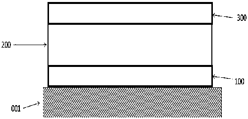
[0042] see figure 1 In this embodiment, 30-100 micron polyacrylic pressure-sensitive adhesive is used as the adhesive layer 100 to be placed on the upper surface of the conventional coating 001 of the fan blade, and 0.5-1% of UV absorber is added to the adhesive layer 100 .

[0043] The protective film layer 200 is placed on the upper surface of the adhesive layer 100, and the protective film layer 200 is made of a transparent single-layer thermoplastic polyurethane material TPU with a thickness of 200-400 microns.

[0044] The paint layer 300 adopts water-based two-component polyurethane paint with a thickness of 100-300 microns.

Embodiment 2

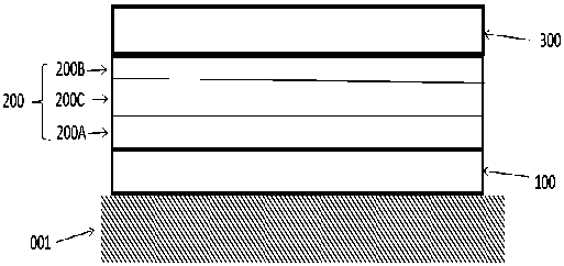
[0046] see figure 2 In this embodiment, a 30-100 micron acrylic pressure-sensitive adhesive is used as the adhesive layer 100 to be placed on the upper surface of the conventional coating 001 of the fan blade, and 0.5-1% of UV absorber is added to the adhesive layer 100 .

[0047] The protective film layer 200 is placed on the upper surface of the adhesive layer 100. The protective film layer 200 is composed of two layers of thermoplastic polyurethane material TPU (the first layer 200A and the second layer 200B), and the thicknesses are 100-300 microns respectively. Acrylic pressure-sensitive 200C with a thickness of 50-100 microns is used as an adhesive layer between two layers of thermoplastic polyurethane material TPU. The three-layer structure together constitutes the protective film layer 200 .

[0048] The paint layer 300 adopts water-based two-component polyurethane paint with a thickness of 100-300 microns.

Embodiment 3

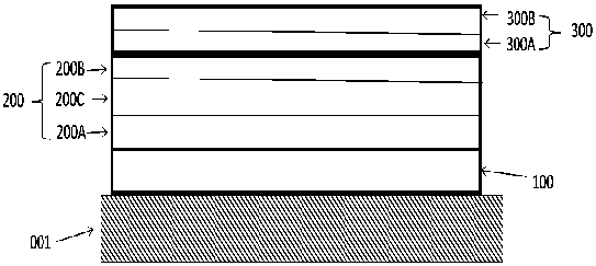
[0050] see image 3 In this embodiment, a 30-100 micron acrylic pressure-sensitive adhesive is used as the adhesive layer 100 to be placed on the upper surface of the conventional coating 001 of the fan blade, and 0.5-1% of UV absorber is added to the adhesive layer 100 .

[0051] The protective film layer 200 is placed on the upper surface of the adhesive layer 100. The protective film layer 200 is composed of two layers of thermoplastic polyurethane material TPU (the first layer 200A and the second layer 200B), and the thicknesses are 100-300 microns respectively. Acrylic pressure-sensitive 200C with a thickness of 50-100 microns is used as an adhesive layer between two layers of thermoplastic polyurethane material TPU. The three-layer structure together constitutes the protective film layer 200 .

[0052] The paint layer 300 adopts double-layer water-based two-component polyurethane paint, and the first layer 300A has a thickness of 50-100 microns and is red. The second lay...


PUM

PropertyMeasurementUnit
Thicknessaaaaaaaaaa

Abstract

The invention discloses a leading edge protecting layer technology for blades of a wind driven generator. The leading edge protecting layer is used for protecting leading edges of the blades of the wind driven generator from being eroded by rainwater. Protecting layers of the leading edge protecting layer technology mainly comprise three layers, namely an adhesive layer, a protective film layer and an oil paint layer which are upward arranged from a conventional coating on the surface of each blade; the lower surface of the adhesive layer is attached to the conventional coating on the surfaceof each fan blade so as to realize the effects of bonding the protective film layer with the blade; the film protecting layer is made of colorless transparent high-elasticity plastic which can be butnot limited to thermoplastic elastomer polyurethane (TPU). The oil paint layer is an epoxy resin or polyurethane/polyurea elastomer coating. According to the leading edge protecting layer technology disclosed by the invention, the rain erosion resistance of the fan blades is greatly improved, and the times of high-altitude maintenance at later stage are reduced.

Description

technical field [0001] The invention belongs to the field of polymer materials and relates to a protective layer technology for the leading edge of a wind generator blade. Background technique [0002] The blades of large wind turbines are made of glass fiber reinforced epoxy resin, carbon fiber and other materials, which have high strength. However, because the linear velocity of the tip of the blade is very high, which can reach more than 300 kilometers per hour, the leading edge of the tip of the fan blade, that is, the windward side, will collide head-on with rainwater, sand and dust, causing serious erosion, resulting in damage to the aerodynamic shape of the blade. resulting in a substantial reduction in power generation efficiency. [0003] In order to prolong the life of the blade and enhance the ability of the blade to resist rain erosion, there are currently two protective technologies: one is the blade protective film solution represented by 3M, and a protective ...

Claims


Application Information

Patent Timeline
IPC IPC(8): C08J7/04C09D175/04C09J133/00B32B33/00B32B27/40B32B27/06B32B7/12
CPCB32B7/12B32B27/08B32B27/40B32B33/00C08J7/042C08J2433/00C08J2475/04
Inventor 纪冬
Owner 萍乡高恒材料科技有限公司
Why Eureka
Try Eureka