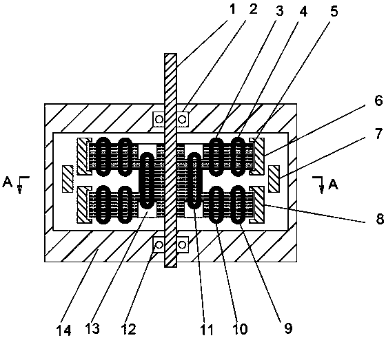
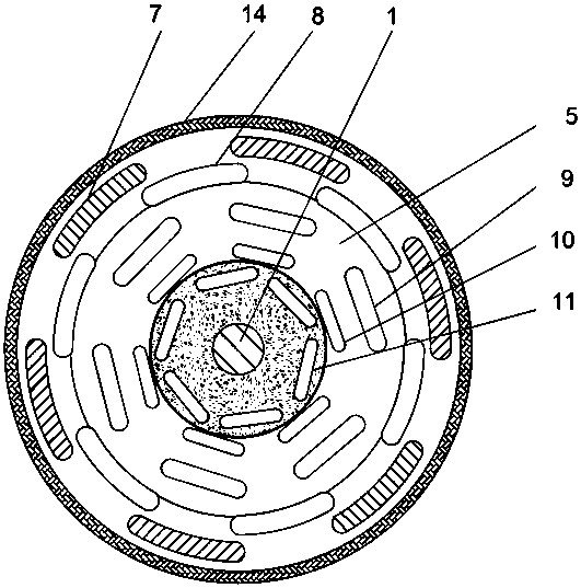
A high-torque motor for multi-rotor drones
A multi-rotor UAV and high-torque technology, which is applied in the field of high-torque motors, can solve problems such as insufficient motor torque and inability to meet torque requirements, achieve linear and stable torque output, facilitate new designs and new modifications, and avoid clearance dead angles Effect
Active Publication Date: 2019-10-01
SICHUAN COLLEGE OF ARCHITECTURAL TECH
View PDF10 Cites 0 Cited by
- Summary
- Abstract
- Description
- Claims
- Application Information
AI Technical Summary
Problems solved by technology
The purpose of the present invention is to provide a high-torque motor for multi-rotor drones, which is used to solve the problem that most of the existing drone motors described in the background technology are driven at high speeds, and for some single-rotor drones When a motor that requires a large torque is matched, there is often a problem of insufficient motor torque; especially for the drive motor of a rotor UAV with a large wing surface, higher requirements are put forward for the torque
Existing high-speed motors cannot meet the torque requirements, especially for modified single-rotor UAVs
Method used
View moreImage
Smart ImageViewing Examples
Examples
Embodiment 1
Embodiment 2
Login to View More PUM
 Abstract
The invention discloses a high-torque motor for a multi-rotor unmanned aerial vehicle. The high-torque motor comprises a shell, a drive shaft, an electric brush and a commutator, wherein the commutator is in contact connection with the electric brush and is arranged on the drive shaft; a middle segment, located in the shell, of the drive shaft is fixedly sleeved with a rotor main body formed by superposing multiple silicon steel sheets; the rotor main body is provided with a winding group formed by multiple windings; and a corresponding permanent magnet group is arranged at the position, closeto the inner wall of the shell, on the outer circumference, employing the drive shaft as the circle center, of any layer of winding in the winding group. The magnetic field can be strengthened underthe condition of the same voltage supply through correspondingly adding the multiple windings and permanent magnets, thereby increasing the torque; and furthermore, multiple layers of windings are arranged along the direction of the drive shaft in a staggered manner, so that the problem of a dead angle in a gap between magnetic force and driving force can be solved and torque output is more linearand stable.
Description
technical field The invention relates to the field of electric motors, in particular to a small-volume, high-torque DC drive motor, specifically, a high-torque motor for multi-rotor drones. Background technique Unmanned aircraft, referred to as "UAV", is an unmanned aircraft controlled by radio remote control equipment and its own program control device. There is no cockpit on board, but equipment such as autopilot and program control device are installed. The personnel on the ground, on the ship, or at the remote control station of the parent aircraft track, locate, remotely control, telemeter and digitally transmit it through radar and other equipment. Under the radio control, it can take off like an ordinary aircraft or be launched into the air with a booster rocket, and it can also be taken into the air by the parent aircraft for flight. When recovering, it can automatically land in the same way as the common aircraft landing process, and can also be recovered by remot...
Claims
Login to View More Application Information
Patent Timeline
 IPC IPC(8): H02K1/17H02K1/22H02K3/28H02K23/36
Inventor 王旭东
Owner SICHUAN COLLEGE OF ARCHITECTURAL TECH
Features
- R&D
- Intellectual Property
- Life Sciences
- Materials
- Tech Scout
- Unparalleled Data Quality
- Higher Quality Content
- 60% Fewer Hallucinations
Learn More Browse by: Latest US Patents, China's latest patents, Technical Efficacy Thesaurus, Application Domain, Technology Topic, Popular Technical Reports.
© 2025 PatSnap. All rights reserved.Legal|Privacy policy|Modern Slavery Act Transparency Statement|Sitemap|About US| Contact US: help@patsnap.com


