Composite flexible element design method

A flexible element and design method technology, applied in design optimization/simulation, calculation, special data processing applications, etc., can solve the problems of no clear design steps for composite flexible element layup, high production cost of non-metallic composite materials, etc.

Active Publication Date: 2018-05-01
刘长喜
View PDF5 Cites 3 Cited by
  • Summary
  • Abstract
  • Description
  • Claims
  • Application Information

AI Technical Summary

Problems solved by technology

And in view of the high production cost of non-metallic composite materials, its design process relies more on CAE analysis software
[0005] However, the design and analysis of flexible components made of non-metallic composite materials in China is still in its infancy, and there is no clear design procedure for the layup of flexible components made of composite materials.

Method used


Image

  • Composite flexible element design method
  • Composite flexible element design method
  • Composite flexible element design method

Examples


specific Embodiment approach 1

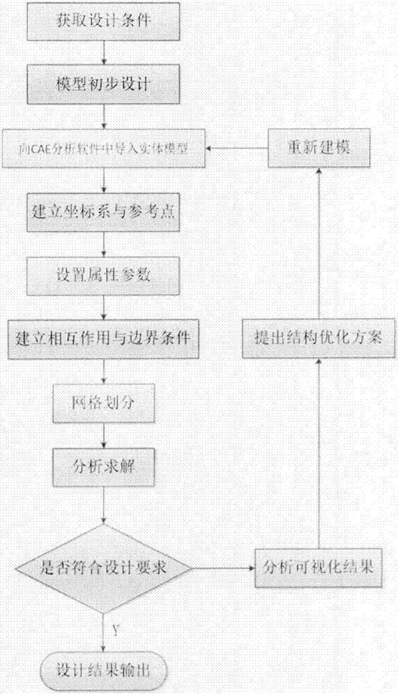
[0030] In the design method of the composite material flexible element of the present embodiment, the design method is realized through the following steps:

[0031] Step 1. According to the structural characteristics and force form of the flexible element, design a preliminary model in the modeling software and save it in a common format;

[0032] Step 1. Analyze the force form and establish the structural characteristics according to the technical parameters required by the flexible components, determine the preliminary size and lay-up design, establish a preliminary model in the modeling software according to the preliminary size and lay-up design and save it as a general Format;

[0033] Step 2. Import the solid model into the CAE analysis software according to the design content of the preliminary model;

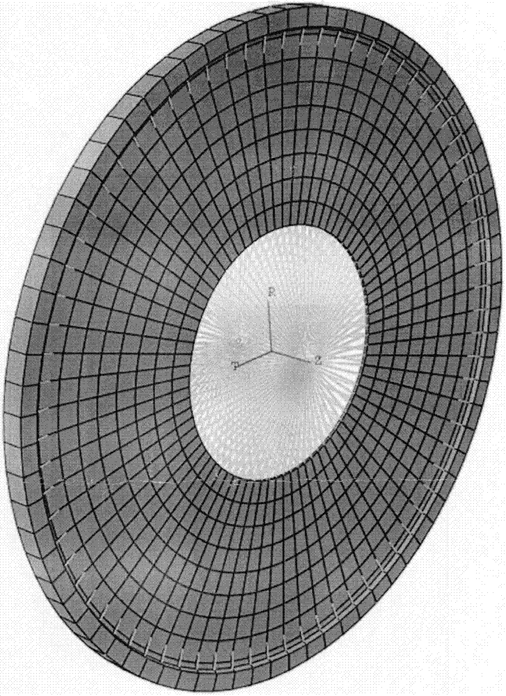
[0034] Step 3, establish a cylindrical coordinate system in the model properties in the CAE analysis software, and establish a reference point on the rotation axis at ...

specific Embodiment approach 2

[0042] The difference from Embodiment 1 is that, in the method for designing composite material flexible elements in this embodiment, the modeling software described in Step 1 is SOLIDWORKS modeling software. OLIDWORKS modeling software is a set of solid model design system, which can analyze the assembly and kinematic relationship of the 3D solid model, reduce errors in the design process to improve product quality, and can perform simple reverse engineering, finite element analysis, and numerical control simulation and other functions.

specific Embodiment approach 3

[0043] Different from the first or second specific embodiment, in the design method of the composite material flexible element in this embodiment, the general format described in the first step is a STEP AP203 format file output by using the SOLIDWORKS modeling software.


PUM

PropertyMeasurementUnit
The inside diameter ofaaaaaaaaaa
Outer diameteraaaaaaaaaa

Abstract

The invention discloses a composite flexible element design method which includes the steps: building a model and storing the model in a general format according to preliminary dimension and lay-up design in modeling software according to technical parameter requirements of a flexible element; leading a solid model into CAE (computer aided engineering) analysis software, building a cylindrical-coordinate system in a model attribute and building a reference point on a rotating axis according to the design content of the preliminary model; setting the attribute, the area and direction parametersof composite layer materials; building coupling constraint and clustering constraint in interaction attributes, and associating the constraint with the built reference point; building condition parameters of applied force and setting boundary conditions; building a hexahedral mesh, inputting living example distribution values and then creating a job file for solution; comparing solved visual results with preliminary design expected results. Design cost can be reduced, design and analysis cycle period is shortened, and an optimal design approach is provided.

Description

Technical field: [0001] The invention relates to a design method of a composite material flexible element. Background technique: [0002] The flexible element has the following characteristics. It can produce significant elastic deformation when it is loaded. On the one hand, it can compensate for relative displacement. Second, it can alleviate the impact by storing elastic deformation. Third, it can be changed through deformation. Structural stiffness, adjust the natural frequency of the system, to avoid resonance and reduce structural noise. Therefore, the torque generated by the driving machine is transmitted to the driven machine through the flexible element. The flexible element is excellent in compensating for large radial, axial and angular offsets, transmitting power, and strong torque capacity. Therefore, it is widely used in industries, Ships, steam turbines, and high-speed centrifugal compressors are widely used. [0003] At present, the classification of flexib...

Claims


Application Information

Patent Timeline
IPC IPC(8): G06F17/50
CPCG06F30/23
Inventor 刘长喜
Owner 刘长喜
Why Eureka
Try Eureka