IC carrier board

A carrier board and substrate technology, applied in the field of IC carrier boards, can solve the problems of difficult heat dissipation of IC carrier boards, achieve excellent flame retardancy and salt spray resistance, solve the effects of difficult heat dissipation, and internal structure protection

Inactive Publication Date: 2018-05-15
杜桂萍
View PDF0 Cites 0 Cited by
  • Summary
  • Abstract
  • Description
  • Claims
  • Application Information

AI Technical Summary

Problems solved by technology

[0004] In view of this, the present invention provides a new type of IC carrier board, which provides assistance to the second IC substrate through a flexible circuit board, and finally implements it on the first IC substrate. This device is more novel in use; The setting of the structure effectively solves the problem that the IC carrier board is difficult to dissipate heat, and the IC carrier board is well protected by the protective coating to solve the problems raised in the above-mentioned background technology

Method used


Image

  • IC carrier board
  • IC carrier board

Examples


Embodiment 1

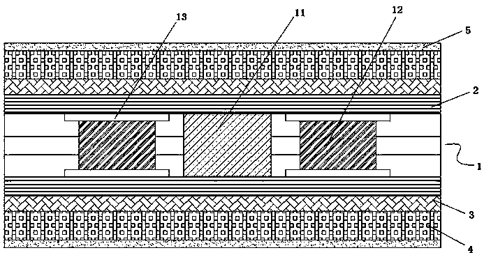
[0020] A kind of IC carrier board, it is characterized in that, comprises ceramic substrate 1, and described ceramic substrate is provided with first IC substrate 11, second IC substrate 12, flexible circuit board 13, and described first IC substrate is arranged on ceramic substrate In the central area, the second IC substrate is symmetrically arranged on both sides of the first IC substrate, and the flexible circuit board is symmetrically arranged on the upper and lower ends of the second IC substrate; layer 2, a second heat dissipation layer 3 is provided on one side of the first heat dissipation layer, an insulating layer 4 is provided on one side of the second heat dissipation layer, and a protective coating 5 is provided on the surface of the insulating layer.

[0021] Further, the first heat dissipation layer 2 is a metal copper heat dissipation layer.

[0022] Further, the second heat dissipation layer 3 is an aramid fiber layer.

[0023] Further, the aramid fiber laye...

Embodiment 2

[0026] This embodiment provides an IC carrier with a structure consistent with that of Embodiment 1. The difference is that the protective coating 5 includes the following components in parts by weight: maleic acid resin 23, methyl methacrylate 13, Epoxy resin 7, azobisisobutyronitrile 6, polyethylene glycol 13, calcium stearate 11, sodium alginate 17, alumina ceramic powder 19, tributyl phosphate 5, dodecyl alcohol ester 7, Polyimide hollow microspheres 36, 1,3-diaminopentane 8, diethanolamine 15, distilled water 62.

[0027] The preparation method of the protective coating in the present embodiment is: the preparation method of coating of the present invention is: maleic acid resin, methyl methacrylate, epoxy resin, azobisisobutyronitrile, polyethylene glycol, After dissolving 1,3-diaminopentane, shake well, heat the shaken solution to 55-65°C, and stir at 150r / min for 45-65min to obtain a mixed solution; mix the remaining components in parts by mass to Disperse at a disper...

Embodiment 3

[0029] This embodiment provides an IC carrier with a structure consistent with that of Embodiment 1. The difference is that the protective coating 5 includes the following components in parts by weight: maleic acid resin 34, methyl methacrylate 21, Epoxy resin 13, azobisisobutyronitrile 13, polyethylene glycol 19, calcium stearate 17, sodium alginate 29, alumina ceramic powder 48, tributyl phosphate 9, dodecyl alcohol ester 11, Polyimide hollow microspheres 53, 1,3-diaminopentane 15, diethanolamine 24, distilled water 89.


PUM


Abstract

The invention provides an IC carrier board which comprises a ceramic substrate. A first IC substrate, a second IC substrate and a flexible circuit board are arranged on the ceramic substrate. The first IC substrate is arranged in the central area of the ceramic substrate. The second IC substrate is symmetrically arranged on both sides of the first IC substrate. The flexible circuit board is symmetrically arranged on upper and lower ends of the second IC substrate. According to the invention, the second IC substrate is assisted by the flexible circuit board, and finally implementing is carriedout on the first IC substrate; the overall performance of the IC carrier board provided by the invention is significantly improved; the heat dissipation structure provided by the invention effectivelysolves the problem of difficult heat dissipation of the IC carrier board; in addition, a protective coating and an insulating layer are well adhered and bonded, and at the same time have the advantages of excellent flame retardant performance and salt spray resistance; and the internal structure of the IC carrier board can be effectively protected.

Description

technical field [0001] The invention belongs to the technical field of circuit board processing, and in particular relates to an IC carrier board. Background technique [0002] At present, the substitutes of my country's printed circuit board industry are mainly manifested in the substitution of sub-industry products, the market share of rigid circuit boards has shrunk, and the market share of flexible circuit boards has continued to expand. The development of high-density electronic products will inevitably lead to higher levels and smaller BGA hole spacing, which also puts forward higher requirements for the heat resistance of materials. In the current strategic transformation period of industrial chain integration and collaborative development and innovation, high-density circuit boards, new functions and intelligence of circuit boards, and the development of light, thin, thin and small products bring about heat dissipation, precise layout, and packaging design. etc. h...

Claims


Application Information

Patent Timeline
Patent Type & Authority Applications(China)
IPC IPC(8): H01L23/498H01L23/373
CPCH01L23/3735H01L23/3736H01L23/3737H01L23/49833H01L23/49894
Inventor 杜桂萍
Owner 杜桂萍
Why Eureka
Try Eureka