Unlock instant, AI-driven research and patent intelligence for your innovation.
Unmanned aerial vehicle obstacle avoidance method
What is Al technical title?
Al technical title is built by PatSnap Al team. It summarizes the technical point description of the patent document.
A UAV and obstacle avoidance technology, applied in the field of UAV navigation, can solve problems such as difficulty in accurate autonomous obstacle avoidance, and achieve the effect of detection and avoidance
Active Publication Date: 2018-05-22
天津萨瑞德科技有限公司
View PDF7 Cites 11 Cited by
Summary
Abstract
Description
Claims
Application Information
AI Technical Summary
This helps you quickly interpret patents by identifying the three key elements:
Problems solved by technology
Method used
Benefits of technology
Problems solved by technology
[0005] However, the above-mentioned applications all have the disadvantage that it is difficult to avoid obstacles accurately and autonomously. Therefore, how to design a new method of obstacle avoidance for UAVs to achieve accurate and autonomous obstacle avoidance is a technical problem that needs to be solved urgently in the prior art.
Method used
Image
Click on the blue label to locate the original text in one second.
Reading with bidirectional positioning of images and text.
Examples
Embodiment 1
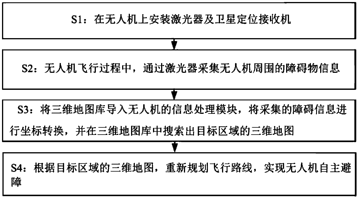
[0058] combine figure 1 , the unmanned aerial vehicle automatic obstacle avoidance method of the present embodiment, comprises the following steps:
[0059] S1: Install the laser and satellite positioning receiver on the drone; in S1, install the laser on the center of the upper end of the drone, and measure the positional relationship between the positioning center of the satellite positioning receiver on the drone and the center of the laser; where , the laser includes a laser transmitter and a laser receiver, the laser transmitter sends laser light to the outside world, and the laser receiver receives the laser light reflected by external obstacles; among them, the satellite positioning receiver can receive any one of GPS, Beidou, Galileo or GLONASS satellite signal;
[0060] S2: During the flight of the UAV, the laser is used to collect the obstacle information around the UAV; Obstacle information collection in azimuth; in S2, two adjacent images collected by the laser a...
Embodiment 2
[0114] The target area searching method of the present embodiment searches out the three-dimensional map of the target area in the three-dimensional map library according to the coordinate information of the obstacle, including the following steps:
[0115] S301. Let f(x, y, z) be the image of the three-dimensional map library, denoted as A, and the size is M×N×L; let g(x, y, z) be the image of the obstacle information collected by the laser, Recorded as B, the size is m×n×l;
[0116] S302. Find sub-blocks matching B in A:
[0117] with S x,y,z Indicates a subblock of the same size as B in A, S x,y,z With (x,y,z) as the upper left corner point, S x,y,z The corresponding matrix is: S x,y,z (k1,k2,k3)=f(x+k1-1,y+k2-1,z+k3-1)
[0118] Among them, k1=1,2...,m; k2,=1,2...,n; k3=1,2...,l;
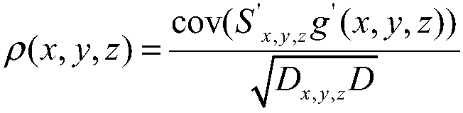
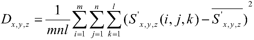
[0119] S303. Obtaining a three-dimensional map of the target area:
[0120] After the above segmentation of the A image of the 3D map library, first, calculate S x,y,z The centroid of the...
PUM
Abstract
The invention discloses an unmanned aerial vehicle obstacle avoidance method, and belongs to the unmanned aerial vehicle navigation field. The unmanned aerial vehicle obstacle avoidance method includes the following steps: S1, installing a laser and a satellite positioning receiver on an unmanned aerial vehicle; S2, during the flying process of the unmanned aerial vehicle, acquiring the information of obstacles surrounding the unmanned aerial vehicle through the laser; S3, importing a three-dimensional map library into an information processing module of the unmanned aerial vehicle, performingcoordinate transformation on the acquired obstacle information, and searching a three-dimensional map of the target area from the three-dimensional map library; and S4, according to the three-dimensional map of the target area, re-planning the flight route and realizing autonomous obstacle avoidance of the unmanned aerial vehicle. The unmanned aerial vehicle obstacle avoidance method aims at overcoming the deficiency that a current unmanned aerial vehicle obstacle avoidance technology is hard to accurately avoid obstacles autonomously, and provides an unmanned aerial vehicle obstacle avoidance method which can implement accurate autonomous obstacle avoidance.
Description
technical field [0001] The present invention relates to the field of unmanned aerial vehicle navigation, and more specifically, relates to an obstacle avoidance method for unmanned aerial vehicles, which can be widely used in aerial photography, electric power inspection, environmental monitoring, forest fire prevention, disaster inspection, anti-terrorism, military Reconnaissance and battlefield assessment and other occasions. Background technique [0002] Research on UAV control technology is one of the hot spots that universities and research institutions at home and abroad are paying attention to. In recent years, unmanned aerial vehicles have become more and more common and have been widely used in various occasions. It effectively overcomes the shortcomings of manned aircraft in the air, reduces maintenance and procurement costs, and increases the flexibility of operations. and adaptability. However, drones often face safety threats from physical obstacles such as mo...
Claims
Application Information
Patent Timeline
Application Date:The date an application was filed.
Publication Date:The date a patent or application was officially published.
First Publication Date:The earliest publication date of a patent with the same application number.
Issue Date:Publication date of the patent grant document.
PCT Entry Date:The Entry date of PCT National Phase.
Estimated Expiry Date:The statutory expiry date of a patent right according to the Patent Law, and it is the longest term of protection that the patent right can achieve without the termination of the patent right due to other reasons(Term extension factor has been taken into account ).
Invalid Date:Actual expiry date is based on effective date or publication date of legal transaction data of invalid patent.

