Flexible optical fiber composite submarine cable and preparation method thereof

An optical fiber composite, submarine cable technology, applied in the direction of submarine cables, insulated cables, communication cables, etc., can solve the problems of heavy weight, inconvenience, increased cost, etc., achieve low eddy current loss and hysteresis loss, high transmission efficiency, high resistance The effect of tensile strength

Pending Publication Date: 2018-05-25
万达集团股份有限公司 +1
View PDF0 Cites 7 Cited by
  • Summary
  • Abstract
  • Description
  • Claims
  • Application Information

AI Technical Summary

Problems solved by technology

[0002] With the in-depth implementation of the country's marine development strategy, the demand for marine cables is becoming more and more diverse. The existing conventional submarine cables cannot meet the needs of flexible DC power transmission in offshore tidal energy, wave energy power generation devices and other marine environments.
The existing submarine cables mainly have the following disadvantages: (1) Lead sheath and steel wire armor structure are usually used. The steel wire and lead sheath of this structure are prone to fatigue and fracture in a long-term turbulent environment, and are not suitable for tidal (2) The safe bending radius of the existing submarine cable is 15 or 25 times the diameter of the cable core, while in the process of tidal power generation or wave power generation, the bending radius of the submarine cable is required to be 8 times the cable core diameter. Core diameter or even smaller range, so that the submarine cable will not be interrupted due to excessive bending during the power generation process; (3) The existing submarine cable is heavy due to the design structure of the metal lead sheath
In order to obtain more kinetic energy for tidal energy and wave energy power generation, it is required to reduce the dragging effect on the power generation device during the power generation process, so the submarine cable with metal lead sheath structure is not suitable for wave energy power generation system; (4) for the existing To improve the tensile strength of submarine cables, a single-layer or multi-layer thick round steel wire armor structure is usually used, which not only increases the cost, but more importantly, increases the weight and size of the product, which brings difficulties and troubles to submarine cable laying and maintenance. inconvenient

Method used


Image

  • Flexible optical fiber composite submarine cable and preparation method thereof
  • Flexible optical fiber composite submarine cable and preparation method thereof
  • Flexible optical fiber composite submarine cable and preparation method thereof

Examples


Embodiment 1

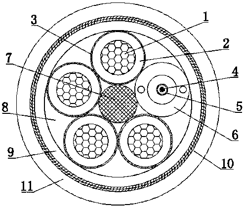
[0024] A flexible optical fiber composite submarine cable, including four power cable cores in the middle, a communication optical cable, and an aramid fiber reinforcing rib 7, and a polyurethane filling layer 8 on the outer layer, an inner sheath layer 9, and an aramid braiding layer 10 and a polyurethane outer sheath 11, the aramid ribs 7 are arranged at the center of the annular circle formed by the four power cable cores and a communication optical cable, and the power cable cores include sequentially from the inside to the outside The fifth category oxygen-free copper flexible conductor 1, nitrile-PVC composite insulation layer 2 and copper wire braided shielding layer 3, the fifth category oxygen-free copper flexible conductor 1 is made of multiple tinned annealed soft copper wire twisted The communication optical cable is provided with a twelve-core optical fiber 4 inside, and the outer layer of the twelve-core optical fiber 4 is sequentially provided with a stainless st...

Embodiment 2

[0041] A kind of preparation method of flexible optical fiber composite submarine cable

[0042] Twist 28 thin round oxygen-free copper wire bundles of 0.4mm into 2.57mm strands with a stranding machine, and then twist 7 strands into a round conductor with an outer diameter of 7.7mm in a 1+6 structure through a frame stranding machine.

[0043] A 120-type extruder is used to extrude 2.2mm nitrile-PVC compound insulation on a 7.7mm round conductor with an extrusion die to obtain 4 insulated wire cores of 12.1mm.

[0044] On the outside of the insulated core, braid the metal shield using a braiding machine. The metal shielding layer is braided with 160 0.2mm copper wires, the braiding density is 57.6%, and the outer diameter after braiding is 12.9mm.

[0045] The high-tensile-strength aramid ribs filled in the middle are made of 42 aramid fiber bundles twisted into 3.1mm strands, and then 7 strands are twisted into 9.3mm aramid ribs in a 1+6 structure.

[0046] 4 insulated cor...


PUM

PropertyMeasurementUnit
elongation at breakaaaaaaaaaa

Abstract

A flexible optical fiber composite submarine cable comprises four power cable cores, a communication optical cable, an aramid reinforcing rib, a polyurethane filling layer, an inner protecting layer,an aramid braiding layer and a polyurethane outer protecting layer, wherein the power cable cores, the communication optical cable and the aramid reinforcing rib are located in the middle, and the polyurethane filling layer, the inner protecting layer, the aramid braiding layer and the polyurethane outer protecting layer are located on the outer side. The aramid reinforcing rib is arranged at thecenter of a torus formed by the four power cable cores and the communication optical cable; each power cable core comprises a class-V oxygen-free copper flexible conductor, a butyronitrile-PVC compound insulating layer and a copper wire braiding shielding layer in sequence from inside to outside, and each class-V oxygen-free copper flexible conductor is formed by twisting multiple tinned annealedsoft copper wires; a twelve-core optical fiber is arranged in the communication optical cable, and the outer layer of the twelve-core optical fiber is provided with a stainless steel tube, a PE protecting bush and a polyurethane protecting layer in sequence; the polyurethane filling layer is arranged between the inner protecting layer and the power cable cores and the communication optical cable.The flexible optical fiber composite submarine cable has the advantages of being good in waterproofness, flexibility and creep resistance, light in weight, small in size, high in tensile strength andthe like.

Description

technical field [0001] The invention relates to the technical field of DC cables, in particular to a flexible optical fiber composite submarine cable and a preparation method thereof. Background technique [0002] With the in-depth implementation of the country's marine development strategy, the demand for marine cables is becoming more and more diverse. The existing conventional submarine cables cannot meet the needs of flexible DC power transmission in offshore tidal energy, wave energy power generation devices and other marine environments. The existing submarine cables mainly have the following disadvantages: (1) Lead sheath and steel wire armor structure are usually used. The steel wire and lead sheath of this structure are prone to fatigue and fracture in a long-term turbulent environment, and are not suitable for tidal (2) The safe bending radius of the existing submarine cable is 15 or 25 times the diameter of the cable core, while in the process of tidal power gener...

Claims


Application Information

Patent Timeline
Patent Type & Authority Applications(China)
IPC IPC(8): H01B1/02H01B5/08H01B7/14H01B7/18H01B7/282H01B11/16H01B11/22
CPCH01B1/026H01B5/08H01B7/14H01B7/18H01B7/1825H01B7/282H01B11/16H01B11/22
Inventor 刘鑫伟刘娅张永东尚吉永孙家伟孙家兴李娜娜王东亮
Owner 万达集团股份有限公司
Why Eureka
Try Eureka