A method that can realize differential control of the flow rate of materials in each phase in a slurry bed reactor

A technology of reactor and slurry bed, which is applied in the field of bioenergy conversion, can solve the problem of less coke, and achieve the effects of no coke polycondensation, simple pretreatment, and wide sources

Active Publication Date: 2020-05-01
BEIJING HUASHI UNITED ENERGY TECH & DEV
View PDF10 Cites 0 Cited by
  • Summary
  • Abstract
  • Description
  • Claims
  • Application Information

AI Technical Summary

Problems solved by technology

[0004] Therefore, the technical problem to be solved by the present invention is to overcome the defects in the prior art that only the use of a coke-absorbing catalyst and a highly active 100-micron-scale coarse particle catalyst can make the amount of coke generated less and relatively improve the use efficiency of the catalyst. Thereby providing a method that can realize the difference control of the flow rate difference of each phase material in the slurry bed reactor

Method used


Image

  • A method that can realize differential control of the flow rate of materials in each phase in a slurry bed reactor
  • A method that can realize differential control of the flow rate of materials in each phase in a slurry bed reactor

Examples


Embodiment 1

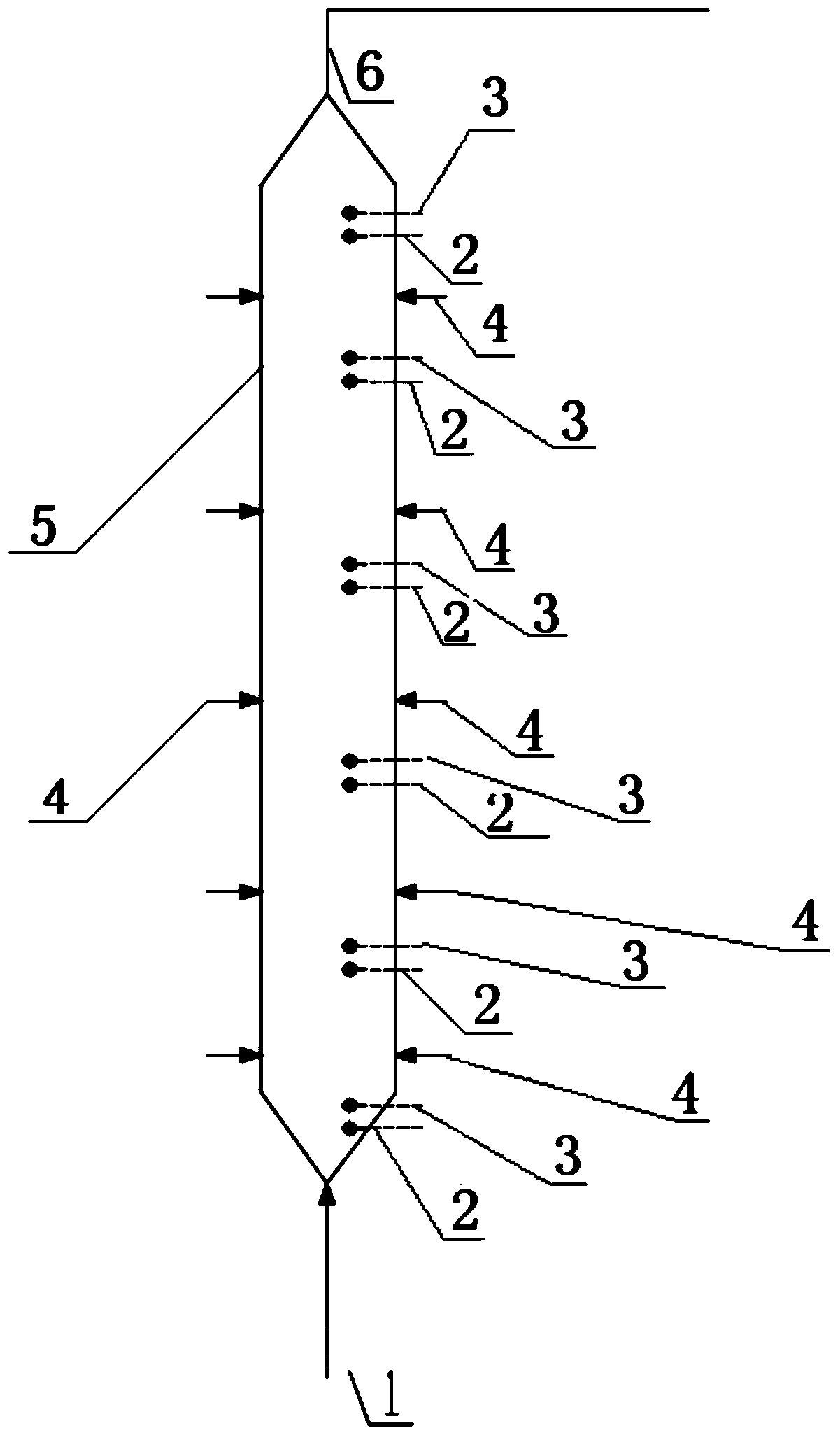
[0037] This embodiment provides a reactor for cracking and hydrogenation controlled by upstream differential velocity, which is a reactor used for the method of controlling the flow rate difference of each phase in a slurry bed reactor, such as figure 1 As shown, the reactor includes a closed shell 5;

[0038] A conical bottom feeding port 1 is located at the bottom of the housing 5;

[0039] A tapered outlet 6 is located on the top of the housing 5;

[0040] The temperature control sensing device 2 and the density measurement sensing device 3 are arranged in pairs on the side wall of the housing 5;

[0041] And the side wall hydrogen injection hole 4, and the side wall hydrogen injection hole 4, the side wall hydrogen injection hole 4 is arranged on the two pairs of the temperature control sensing device 2 and the density measurement sensor arranged in pairs along the cold hydrogen flow direction. On the side wall of the housing between the sensing devices 3.

[0042] The ...

Embodiment 2

[0050] This embodiment provides a method that can realize the difference control of the material flow rate of each phase in the slurry bed reactor. Using the reactor described in Embodiment 1, the aspect ratio of the first reactor used in this embodiment is 15:1. Specific steps are as follows:

[0051] (1) Deash corn stalks with a particle size of 1-50 μm to obtain straw granules, and amorphous alumina loaded with Mo oxides and Ni oxides (with a particle size of 5 μm-50 μm and a specific surface area of ​​150 m 2 / g; the heap specific gravity of the catalyst is 0.8; the average pore diameter of the catalyst is 5nm) and the mixture obtained by mixing the straw particles and sulfur in a mass ratio of 5:100:0.3 is added to medium-low temperature coal tar to form a Substance 10wt% slurry;

[0052] (2) Inject hydrogen at 60°C and 13MPa into the slurry for the first time until the volume ratio of high-pressure hydrogen to the slurry is 50:1, then raise the temperature of the slurry...

Embodiment 3

[0055] This embodiment provides a method that can realize the difference control of the flow rate of each phase in the slurry bed reactor. Using the reactor described in Embodiment 1, the aspect ratio of the first reactor used in this embodiment is 10:1. Specific steps are as follows:

[0056] (1) Reed particles are obtained after deashing reeds with a particle size of 20-1000 μm, and amorphous alumina loaded with W oxide and Ni oxide (with a particle size of 100 μm-150 μm and a specific surface area of ​​200 m 2 / g; the bulk specific gravity of the catalyst is 0.7; the average pore diameter of the catalyst is 30nm) and the reed particles and sulfur are mixed in the ratio of iron oxide, reed particles and sulfur in a mass ratio of 2:3:100:0.4 Obtain a mixture, which is added to vegetable oil to form a slurry containing 30 wt% of biomass;

[0057] (2) Inject hydrogen at 70°C and 20MPa into the slurry for the first time until the volume ratio of high-pressure hydrogen to slurry...


PUM

PropertyMeasurementUnit
specific surface areaaaaaaaaaaa
pore sizeaaaaaaaaaa
particle sizeaaaaaaaaaa

Abstract

The invention discloses a method for realizing differential control of the flow rate of each material phase in a slurry bed reactor, and relates to the technical field of bioenergy conversion. The differential control of the flow rate of each material phase can be realized by arrangement of pairs of temperature control sensing devices and density measurement sensing devices on the side wall of theslurry bed reactor and side-wall hydrogen injection holes arranged between the two pairs of the temperature control sensing devices and the density measurement sensing devices which are arranged upwards along the cold hydrogen flow direction in pairs. The method can ensure the increase of the use efficiency of a catalyst and generation of less amount of coke without exclusive use of a coke-absorbing catalyst.

Description

technical field [0001] The invention relates to the technical field of bioenergy conversion, in particular to a technology capable of controlling the difference in flow rate of each phase of material in a slurry bed reactor. Background technique [0002] Coal, crude oil, natural gas, oil shale and other fossil non-renewable energy sources are becoming increasingly exhausted with the rapid development of social economy, and the CO produced after their combustion 2 , SO 2 , NO x The increasingly serious environmental pollution caused by such pollutants has forced human beings to seriously consider ways to obtain energy and methods to improve the environment. Biomass refers to all directly or indirectly available organic substances formed by the photosynthesis of green plants, including plants, animals, microorganisms and their excretion and metabolites. It is renewable, low-pollution, and widely distributed. Biomass is a kind of renewable energy, which has great potential a...

Claims


Application Information

Patent Timeline
Patent Type & Authority Patents(China)
IPC IPC(8): B01J8/18C10G1/08
CPCB01J8/0005B01J8/18B01J2208/00044B01J2208/00584C10G1/06C10G1/08C10G2300/1011
Inventor 林科李林郭立新崔永君江莉龙
Owner BEIJING HUASHI UNITED ENERGY TECH & DEV
Why Eureka
Try Eureka