Integrated device and method for denitration and dioxin removal of sintering flue gas and utilization of waste heat
A technology for removing dioxins and sintering flue gas, which is applied in the field of sintering flue gas denitrification and dioxin removal and sintering flue gas waste heat utilization, sintering flue gas denitrification, dioxins, and waste heat utilization integrated devices, which can solve operating costs High, energy consumption and other issues, to achieve the effect of prolonging life
- Summary
- Abstract
- Description
- Claims
- Application Information
AI Technical Summary
Problems solved by technology
Method used
Image
Examples
Embodiment approach
[0069]According to the first embodiment of the present invention, an integrated device for sintering flue gas denitrification, dioxin removal and waste heat utilization is provided:
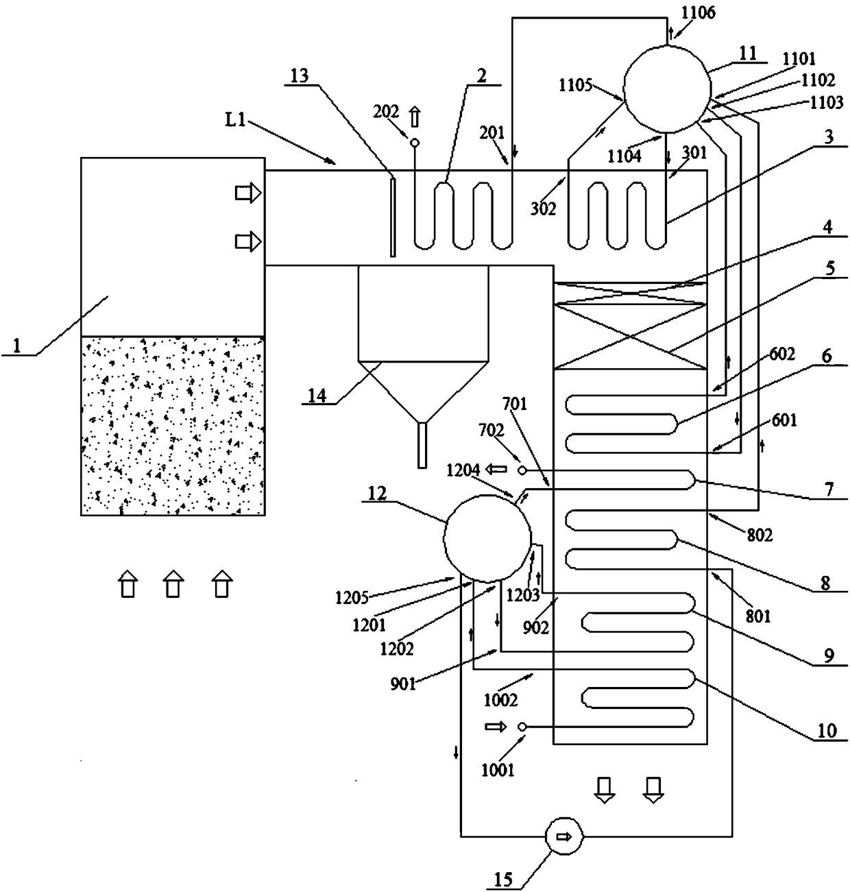
[0070] An integrated device for sintering flue gas denitration and dioxin removal and waste heat utilization, the device includes a sintering cooler 1 and a flue gas pipeline L1 communicating with the sintering cooler 1 . According to the flue gas flow direction, the flue gas pipeline L1 is equipped with a high-parameter superheater 2, a first high-parameter evaporator 3, an ammonia injection grid 4, an SCR reactor 5, a second high-parameter evaporator 6, and a low-parameter superheater. 7, high-parameter economizer 8, low-parameter evaporator 9 and low-parameter economizer 10. The device also includes a high-parameter drum 10 and a low-parameter drum 11 arranged at the side of the flue gas pipeline L1. The outlet 1002 of the low-parameter economizer 10 is connected to the first inlet 1201 of th...
Embodiment 1
[0108] like figure 1 , an integrated device for sintering flue gas denitrification, dioxin removal and waste heat utilization, the device includes a sintering cooler 1 and a flue gas pipeline L1 communicating with the sintering cooler 1 . According to the flue gas flow direction, the flue gas pipeline L1 is equipped with a high-parameter superheater 2, a first high-parameter evaporator 3, an ammonia injection grid 4, an SCR reactor 5, a second high-parameter evaporator 6, and a low-parameter superheater. 7, high-parameter economizer 8, low-parameter evaporator 9 and low-parameter economizer 10. The device also includes a high-parameter drum 11 and a low-parameter drum 12 arranged at the side of the flue gas pipeline L1. The outlet 1002 of the low-parameter economizer 10 is connected to the first inlet 1201 of the low-parameter drum 12 . The first outlet 1202 of the low parameter drum 12 is connected to the inlet 901 of the low parameter evaporator 9 . The outlet 902 of the ...
Embodiment 2
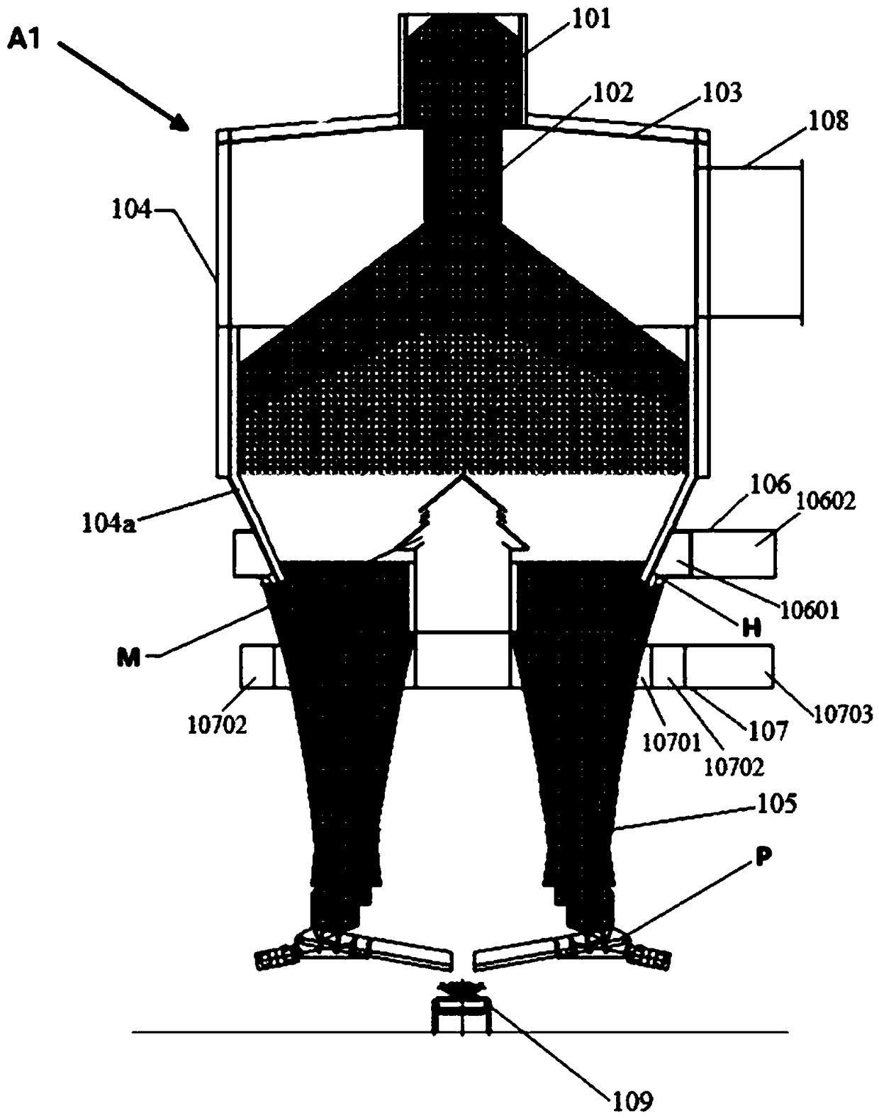
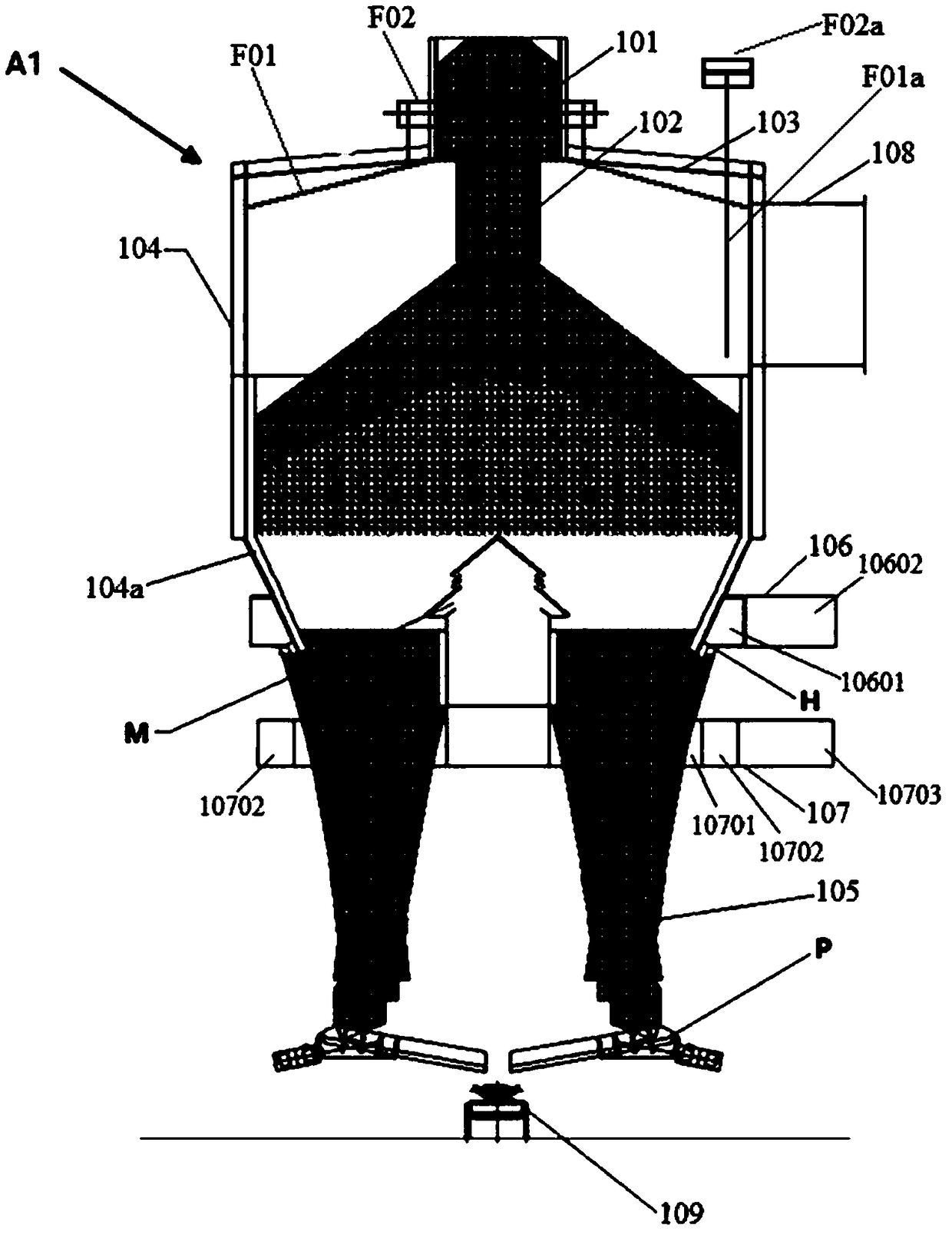
[0126] Repeat Example 1, just as image 3 , the vertical cooler A1 is provided with a first radiant heat recovery device F01 below the tower top cover 103 and close to the tower body top cover 103 . At the front end of the hot air outlet 108, a second radiant heat recoverer F01a is provided. like Figure 10 , the first radiant heat recovery device F01 adopts a fan-shaped hollow plate. like Figure 11 , the second radiant heat recovery device F01a adopts a tube-and-tube heat exchanger.
PUM
 Abstract
Description
Claims
Application Information
 - R&D
- Intellectual Property
- Life Sciences
- Materials
- Tech Scout
- Unparalleled Data Quality
- Higher Quality Content
- 60% Fewer Hallucinations
Browse by: Latest US Patents, China's latest patents, Technical Efficacy Thesaurus, Application Domain, Technology Topic, Popular Technical Reports.
© 2025 PatSnap. All rights reserved.Legal|Privacy policy|Modern Slavery Act Transparency Statement|Sitemap|About US| Contact US: help@patsnap.com


